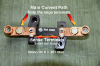
The SHUNT is a very low value resistor with 4 Terminals. Why 4 terminals? Two of them get small wires attached to them and the resistance between those terminals is very controlled. If it's a 50 mV shunt for 100 A, then the resistance is 0.050/100. The other HUGE terminals is where you attach your heavy wire.
A Hall effect sensor depends on the current being measured and a fixed magnetic field. This generates a voltage that is signal conditioned. For a 3 dimensional solid that exhibits the properties, the vectors (magnatude, direction) are perpendicular to the edges.
The Digital Panel Meter gets tricky because it's circuitry doesn't like sharing ground hence the need for an isolated power supply.
OP said:
Yeah I figured it worked similar to that, just did not appear that way. So would I have to worry about my nonstandard 36v if I just go with an analog meter?
No. An analog meter is internally a very sensitive current meter, like 50 uA. it's configured to read a voltage because of a series resistor. Scales are drawn on the meter face for whatever engineering units that are desired. No external power is required. Not sure how well mechanical movements hold up under vibration and humidity.
OP said:
Like if I found a 50A > analog meter (includes shunt), would it be as simple as hooking it up in series with my motor, and I'm done? Or will I still probably have to use a regulator of some sort?
I gave you one such link for a 100 A analog meter and shunt. Both have to be purchased separately from the same source. No power source is required.
Standard power supply voltages are 5, 12, 15, 24 and 48 V. There are some voltages below 5 V that are becoming standard too. the lower the voltege, the lower the power required to operate. The next set of standards are multiples of the dry cell (1.5 V). Way back when 6.3 VAC, 22.5, 45 and 300 V were standard.
")