If I may, could I please revisit a beginner's question from 12.Mar.2008?
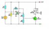
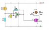
Please find attached sketches of two circuits, before and after. The "after" picture encorporates changes suggested by on1aag, which:
1. changes the "after" circuit to stop the pump at temperatures above something set by P1 (140 degrees F, in my case);
2. smooths hysteresis; and
3. uses an IRF540 (or similar) MOSFET to switch on/off a 12VDC 500mA pump, where a small-signal 2N2222 transistor had been used previously to switch on/off a 500mA relay.
As a novice, I took all this as wisdom from my elders; that is, as a cookbook recipe. Now, making a second pass but still as a novice, I'm trying to understand why the MOSFET was chosen.
There seem any number of "power" transistors, like the TIP31A, that could carry the required current. Some textbook suggested that the transistor loses voltage. Was the MOSFET chosen because it would maintain the 12VDC from drain to source? Or is there some obvious difference between relays and pumps that makes the MOSFET more attractive? All things being equal, transistors seem cheaper, less prone to ESD damage, and easier to acquire.
From scratching my head over the textbooks, I'd like to ask one other question too, if I could, please. In the "before" picture, the books tell me the size of the R5 resistor is chosen relative to the minimum hfe (or beta, or DC current gain) of the transistor. But on the datasheets, the hfe never shows for the voltages I'm using, 5V or 12V. They'll show hfe for 100mA and 1V, they show for 1A and 4V, but never for 500mA at 12V. How do I do that conversion?
Thanks very much.

")
