Continue to Site

Welcome to our site!

Electro Tech is an online community (with over 170,000 members) who enjoy talking about and building electronic circuits, projects and gadgets. To participate you need to register. Registration is free. Click here to register now.

  • Welcome to our site! Electro Tech is an online community (with over 170,000 members) who enjoy talking about and building electronic circuits, projects and gadgets. To participate you need to register. Registration is free. Click here to register now.

Beginner - Where to start

Status
Not open for further replies.

burg

New Member
Hello all,

I've been looking around these forums for the past view days, just reading and trying to figure out a few things. I hope to start building circuits of my own soon, but I admit I have a lot to learn.

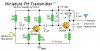
The picture attached is a transmitter I have been thinking of building, but I don't know what some things are.

First of all, I see the 9V battery, but how is that attached? Where does the positive/negative connectors go to?

And when grounding the circuit, how do I go about doing that?

What is L1? I'm pretty sure it is a coil, but what are the details, its purpose?

What about Q1 and 2? What are they for, FM adjustors?

I know these seem like simple questions, but I don't know where else to begin.

Thanks a lot!
 

Attachments

  • FM transmitter.JPG
    FM transmitter.JPG
    24.4 KB · Views: 244
The 9v battery attaches by wiring the positive terminal of the battery to the obvious +9V connection point shown and the negative terminal of the battery to the node labelled "ground".

Ground, in a circuit like this is really just another word for "circuit common" which is another term for Battery-. You don't need to connect ground to anything besides the components shown in the schematic. Since this is a high frequency circuit, it is necessary to keep your ground connections short. Of course, as a beginner you don't know how short is short, so use the value of one half inch for now. The higher the frequency, the shorter the ground connections need to be.

As you rightly observed, L1 is an inductor. Like capacitors, we use inductors for temporary storage of field energy, magnetic field for inductors and electrostatic field for capacitors. In this case, the capacitors C4 and C5 are working with the inductor to trade charge storage back and forth on each cycle of the AC at 100 MHz. When you pick the right values of L and C in such a "tank" circuit, the energy storage of the inductor equals the energy storage of the capacitors and the circuit "resonates". When the circuit resonates, you get some interesting things happening, like for example, this particular stage "oscillates" which in fact is what actually generates your FM carrier at 100 Mhz. As you vary the value of C4 or the value of L1 you will vary the resonant frequency and thus will vary the frequency of oscillation, and in turn will move your FM carrier up or down the radio dial.

Q1 and Q2 are the most important components in your transmitter since they are the "amplifiers". These components have the ability to make a small signal bigger. I should not have called Q2 an amplifier because it is confusing to the beginner, but in fact it is an ampifier that is configured to oscillate as mentioned above. So we normally just refer to that stage as an oscillator. There I go using more jargon. You should also learn the word "stage". By this I mean a functional block that is composed of several components. For example, Q1 does not work by itself, it needs support from R2, R3, R4 and R5 to actually work as an amplifier. When I refer to the amplifier Q1 I really mean the stage that includes Q1, R2-R5, and in fact even C1 and C2 which help connect signals from one stage to another. So, to answer your question, Q1 is an audio amplifier that boosts the microphone audio up to a higher AC voltage, and Q2 is your high frequency oscillator that generates the carrier signal at around 100 Mhz. When the audio feeds into the stage composed of Q2, R6, R7, C3, C4, C5 and L1 it will Frequency Modulate the oscillator with your voice audio.
 
Last edited:
Wow, thanks for the detailed response :)

So when assembling this type of circuit on a protoboard, the ground connects to a rail, and all of the components that are connected to the ground in the diagram connect to the rail? (rail, if thats what it is really called, is the line that is shared with all the holes in that row).

L1, and in general inductors, are quiet similar to a capacitor in the sense that they store the charge, correct? So when the microphone picks up sound, the stored energy, which acts faster than the battery? allows the "amplifiers" to pulse and therefore make a strong signal?

And an outside question - Is this a good circuit to start with? Or do you have any suggestions on other circuits?

Thanks again!
 
You seem to have the right idea about the rail. Except I don't like when you say "the ground connects to a rail, and all of the components that are connected to the ground...". In fact the rail IS the ground. The ground is that single point, or that rail, that you connect the bottoms of the all those components on the schematic that are shown connected to ground. Remember that I said the "ground" is simply the circuit common. In this circuit, the common is the bottom horizontal line in your schematic.

As for your explanation about the inductor, no I don't think you have it right. Its actually quite an advanced concept and I'm wondering if it is too early for you to worry about it. But I'll try again anyway. The charge storage that is being traded between the inductor and mainly C4 is happening at a very high frequency, about 100 MHz in fact. There is really not much relationship between this fact and the energy that comes from the microphone. The oscillator will oscillate whether you have the microphone hooked up or not so you can consider the audio amplifer and its microphone to be completely separate from the oscillator. They do interact a tiny bit to create the Frequency modulation that you want, but it is a very subtle interaction. So the inductor is working as part of the oscillator to create the carrier for your transmitter. Oh boy, I just realized you probably don't know what a carrier is and exactly what frequency modulation is. Its too much to explain here, so maybe you should look these up in a book.

I'm not really sure if this is a good starter circuit or not. Its not very complicated but is more advanced than many other circuits that you could try. For example, when I was taking my first electronics course in high school one of the popular circuits to build was a "color organ". We also built simple things like speaker switches and so on. All the circuits we built at that time operated at low frequencies like audio, or simply did control functions like turning things on and off. I remember we would get our circuits working even though we didn't understand how they worked and it was possible because we avoided complicated stuff like high frequencies, low noise, high power and such circuits. So, I guess I'm saying that this isn't too tough a circuit to build and get to work, but it is a tough one to fully understand. So just build and make it work. If you need to understand every detail, then maybe start with something simpler.
 
I'm not sure what you mean by protoboard, but whatever you do, don't assemble this on breadboard (the one where you stick the components in the holes w/o soldering) it won't work.
 
That's a good point. High frequency circuits don't work on these, what I would call plugboards. These are the white plastic "no solder" prototyping boards that we use with leaded parts. I've got two different types so I just measured the capacitance between terminals. I got 2.6 pF for one model and 2.8 pF for the other. Both of these values are quite high and not tolerable when building high frequency circuits. At 100 MHz this is only about 550 ohms, which isn't much, so your row to row isolation is pretty poor. I've even had problems with digital circuits on such boards where my fast rise and fall times couple across to high impedance nodes in other parts of the circuit. Even just making an RC oscillator with the common two gate circuit was tricky because of the high impedances involved. I've moved to mostly using bare pcb and cutting the solder islands apart with a dremel tool or a knife. This method is fast and reliable.
 
maybe something simpler

While the FM transmitter doesn't seem too complicated you might try something simpler to start with. As already surfaced in this thread are the complexities of radio frequency work - or the relatively simple (but not simple if you've never done it) issues like "ground" or where to connect the battery.

I have to say that over the years Radio Shack has published some books that can help get you started. While the things you build aren't particularly useful by themselves the learning is what is important. Getting some LEDs to blink may not seem like much of an accomplishment but for many of us it is progress toward something more complicated.

Don't overlook some of the products that seem like toys where you can build 100 different circuits from the parts provided.
 
x2 on starting with something easier. You'll feel alot better when you get a simple circuit to work before you try more advanced things like radio transmitters etc.. Don't be discouraged even if your simple project doesnt work right the first time. It takes alot of practice. Consider the easier project a confidence builder before you try something tougher.

Oh yeah, that plugboard stuff can still be useful but only use it on low frequency designs.
 
I agree with starting simple. Use two diodes, a resistor and an LED to make an AND gate and see how that works. Use one transistor, two resistors and an LED to learn how to wire a transistor in common-emitter, common collector and common base configurations. Do some other simple experiments. When you are ready for the bigger projects, you will understand the whys better.

A good beginner website is www.play-hookey.com

He not only teaches theory, but gives step-by-step instruction on breadboarding (using what you have) projects.

Good luck, see you around

AllVol
 
Last edited:
Another thing with this circuit is that the antenna is connected fdirectly to the LC tank circuit, this is bad because the frequency will change as the load changes, (i.e if you walk in front of it the frequency will change slightly). You can avoid this by connecting a small RF amplifier to it and attatching the antenna to that, this will isolate the changes in load to the transmitter.
 
Status
Not open for further replies.

Latest threads

New Articles From Microcontroller Tips

Back
Top