Apologies for this stream of questions. I do hope the answers are of general interest to novices.
I was hoping someone could give me a few tips about trouble-shooting. My first attempt to solder a circuit does not work.
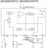
It's supposed to be a DC-to-DC step-down voltage converter, reducing 14V to 12V. As expected, my voltmeter measures Vin to GND(in) at about 17V. Not as expected, it measures Vout to GND(out) at about 0.03V. Whether or not the input voltage is applied, I still get 0.03V.
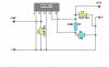
Attached are two pictures, what Rohm suggests and what I (think I) built. But they do not represent very well my inability to control the soldering iron, or the number of perf board holes whose copper-clad rims were unnecessarily filled with solder. I even bent the leads of the BA00BC0WT, two holes between the leads, to get a bit of distance between solder points. As built, the nodes between R2 and C1 are not as distinct as the drawing would lead you to think.
When I saw the 0.03V output, I took ericgibbs's advice to another trouble-shooting question, and looked up the references.
I don't smell or see any burnt components. I'm afraid to apply anything more than a short burst of input voltage, so the tests I made are mostly with an ohmmeter. I connected a 100-watt light bulb across each capacitor before taking my measurements.
GND(in) to GND(out) = 0 ohms. I take this as a good sign.
BA00 pin 1 to GND(out) = 0 ohms
BA00 pin 3 to GND(out) = 0 ohms
Pin 4 to GND(out) = 0 ohms
Vin to pin 2 = 0 ohms
GND(in) to pin 4 = no reading
Pin5 to GND(out) = 35K ohms
And then, some very unexpected readings.
Across the leads of R2 = ohms continually increasing!
Across the leads of R1 = ohms continually increasing!
Pin3 to Vout = increased in the range of 300K while I was measuring
Pin5 to Vout = cycles 72K to 110K ohms and back to 72K!
Any obvious advice or next steps? Any hunches?
Thanks once again.
I was hoping someone could give me a few tips about trouble-shooting. My first attempt to solder a circuit does not work.
It's supposed to be a DC-to-DC step-down voltage converter, reducing 14V to 12V. As expected, my voltmeter measures Vin to GND(in) at about 17V. Not as expected, it measures Vout to GND(out) at about 0.03V. Whether or not the input voltage is applied, I still get 0.03V.
Attached are two pictures, what Rohm suggests and what I (think I) built. But they do not represent very well my inability to control the soldering iron, or the number of perf board holes whose copper-clad rims were unnecessarily filled with solder. I even bent the leads of the BA00BC0WT, two holes between the leads, to get a bit of distance between solder points. As built, the nodes between R2 and C1 are not as distinct as the drawing would lead you to think.
When I saw the 0.03V output, I took ericgibbs's advice to another trouble-shooting question, and looked up the references.
I don't smell or see any burnt components. I'm afraid to apply anything more than a short burst of input voltage, so the tests I made are mostly with an ohmmeter. I connected a 100-watt light bulb across each capacitor before taking my measurements.
GND(in) to GND(out) = 0 ohms. I take this as a good sign.
BA00 pin 1 to GND(out) = 0 ohms
BA00 pin 3 to GND(out) = 0 ohms
Pin 4 to GND(out) = 0 ohms
Vin to pin 2 = 0 ohms
GND(in) to pin 4 = no reading
Pin5 to GND(out) = 35K ohms
And then, some very unexpected readings.
Across the leads of R2 = ohms continually increasing!
Across the leads of R1 = ohms continually increasing!
Pin3 to Vout = increased in the range of 300K while I was measuring
Pin5 to Vout = cycles 72K to 110K ohms and back to 72K!
Any obvious advice or next steps? Any hunches?
Thanks once again.