Continue to Site

Welcome to our site!

Electro Tech is an online community (with over 170,000 members) who enjoy talking about and building electronic circuits, projects and gadgets. To participate you need to register. Registration is free. Click here to register now.

  • Welcome to our site! Electro Tech is an online community (with over 170,000 members) who enjoy talking about and building electronic circuits, projects and gadgets. To participate you need to register. Registration is free. Click here to register now.

beginner: rule of parallel circuits

Status
Not open for further replies.

nyoo

Member
Hi,

I'm trying to refine a simple circuit design, barely armed with Ohm's law and a thin understanding of the Rule of Parallel Circuits. Please could someone help with a couple of novice questions?

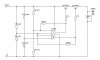
The attached design, using B57891M103J thermistors, is intended to switch on the relay if two conditions are met:
- Th1-tank indicates a temperature greater than 32 Celsuis (or, Th1's resistance is less than 7.5K Ohm); and
- panel is hotter than tank (or, Th2-panel shows less resistance than Th1-tank).

I'll assume the usual convention of IN1/OUT1 and IN2/OUT2 referring to the two halves of the dual opamp.

My scant knowledge of electronics breaks down on that line between the "tank" potential divider and IN1-.

Here's a snippet from the thermistor's data sheet, for an example.
Celsius Ohms
30 8080
32 7432
34 6843

At 30 Celsius, the "tank" potential divider will give 6.22V. By the Rule of Parallel Circuits, I believe that 6.22V will reach both IN1- and IN2+. Do I have that right? If not, could someone please sketch the voltages?

Then, I'd like some hysteresis, limited by the 200K-B, from OUT2 pin IN2+. But I'm worried that the way I've laid this out, I'm also providing unwanted hysteresis to IN1-. Will I be? If so, could someone please suggest a solution?

Thanks very much.
 

Attachments

  • diffthem3.JPG
    diffthem3.JPG
    26.4 KB · Views: 166
Hi,


It looks like you have a 'wired and' circuit there, where both comparators have
to have the correct voltage input to turn the relay on, and the comparators
function as a 'window comparator'.
You are right in that negative feedback is not wanted here, and the way to
get around that is to isolate the second comparator input from the first with
maybe a 10k resistor. This still allows some negative feedback, but since it
is less than before it means the positive feedback is dominant.
But, if the input window width is greater than the hysteresis you wont need
this extra resistor.
Since you have a wired and circuit though, there is an easier way to get there
that only requires one transistor. The transistor would be an NPN though,
and you can then connect both comparator outputs together to get the
wired and function. You also have to invert all the inputs.
This gives you the same functions, just with a simpler circuit.
The NPN emitter would go to ground, with the collector to the relay, and
the other end of the relay to 12vdc.
 
Last edited:
I think you have a more fundamental problem in that the phase of your circuit is incorrect.

If the thermistor heats up, its resistance goes down, pulling down the input of the comparator. If the -ve input of the comparator goes low, the output goes high. this will NOT switch on your pnp transistors. Surely you want to connect the thermistor to the +ve input of the comparator....

Regarding your hysteresis, you have this correct. Not sure about the feedback resistor, but it looks OK. Hysteresis acts to enforce the condition you are trying to meet. When your thermistor input is going low, the comparator trips... Now you want your hysteresis to emphasis this trip point, so it should either take your reference point higher (to make your thermistor trip point lower - thus emphasising your comparator trip conditions), or take your thermistor input lower (doing the same). Hysteresis is always added to the +ve input (otherwise you get negative feedback not positive), so you need to take your 220k resistors back to the +ve inputs.

So, apply your thermistors to the +ve inputs of your comparators (to get the phase of your transistor drive correct), then apply hysteresis back to the +ve inputs of your comparators.

Personally I would also put a 1uF capacitor across your 10k resistor divider chain, just to keep that point nice and stable
 
Hi,

Thanks for your encouragement.

First a basic correction, and my apologies. (I was so excited by coming up with a 2-thermistor solution, I got mixed up!)

The statement of the problem should have read: with only 2 thermistors,
1. switch on the relay if the tank is cooler than 60 Celsius,
2. but only switch it on if the tank is also cooler than the panel.

After some calculation, I believe the "tank" potential divider should go to the +ve, in both cases.

MrAl's 2nd suggestion sounded like a good direction to go; attached is the resulting circuit.

ElectronWorks suggested hysteresis on the +ve inputs, which I have followed.

I am still left with 3 questions.

1. This circuit assumes the relay will switch on, only if both OUT1 and OUT2 from the IC give non-zero voltage? Why wouldn't the relay switch on if only one output has non-zero voltage?

2. Not sure where the ElectronWorks' 1uF capacitor goes. Could someone please help?

3. Have I attached this hysteresis back at the proper point?


Thanks again.
 

Attachments

  • diff therm 20090914.JPG
    diff therm 20090914.JPG
    25 KB · Views: 161
Last edited:
Status
Not open for further replies.

New Articles From Microcontroller Tips

Back
Top