Two very basic questions.
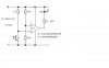
Are there two ways to solder this?
Apologies for an absolutely basic question. See two circuits attached. Are these circuits equivalent? My beginner's reading of Kirchoff's Current Law would lead me to believe these two are the same. (Needless to say, I'm laying out the components on a perf board, and version B fits better, but version A was specified.)
A general replacement for the UA741?
The op amp for most simple "hobby" circuits seems to be the UA741 or LM741. The LM741IP (good below freezing, DIP-8 package) version, is now beginning to be scarce.
For 5-18V supply,
in a DIP-8 package
with low risk of ESD,
where slew rate is not important,
but temperature range is important,
and priced economically,
what's your preference?
Does the TL071IN make the running?
And which electrical characteristic on the datasheet is key to this comparison? Is it Output Current?
Thanks very much.