Continue to Site

Welcome to our site!

Electro Tech is an online community (with over 170,000 members) who enjoy talking about and building electronic circuits, projects and gadgets. To participate you need to register. Registration is free. Click here to register now.

  • Welcome to our site! Electro Tech is an online community (with over 170,000 members) who enjoy talking about and building electronic circuits, projects and gadgets. To participate you need to register. Registration is free. Click here to register now.

Battery Charger help! (sch included)

Status
Not open for further replies.
I'm glad we've cleared most of my misconceptions up.

I assumed that there should be no voltage out without a load (battery) connected. Upon testing it, I find it does have voltage that seems to be dependent on VR1 even with no load.

I've had my current battery on the charger all morning. It started at 11.8V and is now at 13.3V. I do notice a slight humm or buzz coming from either the Q4 or CR5. Its an eerie sound despite its low volume.

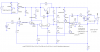
On the charger board on test (while charging), I measure Q4's terminals.
B - 14V
C - 14.1V
E - 15.35V

If the problem is Q4, I have a whole LOT of bad parts then. I've tested at least 6 boards to find the same traits, I have probably a box of 75 of these things left to test.

I am really considering stopping the current charge so I can change the setting of VR1 via the output of the charger with no load. (13.8). If I do disconnect it I will be sure to see what the set point is with no load as it is now.
 
Cloud9, you earlier said,
Additionally I am baffled as to why I have 13+V on every pin of Q4 regardless of charge state or charge threshold. Peculiar.
That doesn't jibe with what you are now measuring. How come?
And, as I said before, I really need to know the voltage on the emitter of Q4, with no battery on the charger, before I can run any more simulations.
 
Brian Hoskins said:
So does the output voltage need to be set 0.7V above the required voltage to ensure the regulator only drops out when the required battery voltage is achieved?

Brian
No, the saturation voltage plus the voltage from the rectifier only determine how high you can set the setpoint. There is a diode in series with the battery, so it is important to measure the voltage across the battery as opposed to at the collector if you want to know the true state of charge. The current sense resistor R6 also contributes a substantial error if the battery is charging.
 
On the emitter of Q4, with no load, I get 16.83V which is the raw output voltage of the Bridge Rectifier (BR1)

15.67V on Base

Not even 1/10 of a volt on the Collector
 
Cloud9 said:
On the emitter of Q4, with no load, I get 16.83V which is the raw output voltage of the Bridge Rectifier (BR1)

15.67V on Base

Not even 1/10 of a volt on the Collector
OK, thanks.
 
Cloud9 said:
Shouldnt we expect some voltage on the collector even if q4 is off due to the V+ thru R19?
I'm wondering the same thing. In my sims, the circuit is active even with no battery connected to it.
 
I can't see any way there would be 0 volts on the collector. If Q4 is completely off, you would still have bias from R19 which should result in about 6.8 V on the collector.

And with at least 6.8 v on the collector, I see there would be some bias to the base of Q4 so it would start to turn on a bit and increase the output voltage, so it must stabilize to something higher than 6.8 V.
 
Last edited:
RadioRon said:
I can't see any way there would be 0 volts on the collector. If Q4 is completely off, you would still have bias from R19 which should result in about 6.8 V on the collector.
Yes, and I believe the initial bias from R19 is required to guarantee that the loop will start.
 
Roff said:
Yes, and I believe the initial bias from R19 is required to guarantee that the loop will start.

Good point. Otherwise, Q3 would never get any bias to get things going. I see.

I don't believe that Cloud9's measurement of 0 volts was correct, if there are no faults on the board. Are there?

Just speculating, but if CR2 was faulty or wrong (too low voltage) would we perhaps see some of the reported symptoms?

Another bit of info for Cloud9: when trying to debug a feedback system such as this, the classic method is to open the feedback loop at any convenient point and inject a signal into the opened part (the input that you just created by breaking the loop) and monitor the other part (the output that you just created by breaking the loop) for an expected response.
 
Last edited:
I re-measured the collector Q4, on a no-load charger and found:
14.53V - Perhaps I had a bad connection ealier (damn conformal coating). My apologies.

That makes more sense now. RadioRon, I would expect more than 6.8V because R19 is tied to V+ which is 16.7V


My battery that has been on all day is just now at 13.78V. The speed of charge above 13V is sloooow. Would it be foolish to leave this thing connected overnight?
 
Aha, that's more like it. Could it be that everything is working properly and we simply don't have a good procedure for setting VR1 yet and that's all?

I would not leave this charger overnight unattended until you are sure it is working perfectly.

I'm curious, now that you are up to 13.78 V is the fastcharge LED still illuminated? And for that matter, why have you not set up to monitor the current flowing into the battery? This would be very useful info. In fact, I don't think you have finished your job until you have plotted current vs time and voltage vs time for a typical battery charge cycle with a given setpoint. Such a plot of current vs time should show you an abrupt change in charge current as the voltage slowly approaches its setpoint value, and it is this abrupt change that is your long sought "shut off". Monitoring voltage alone will not give you any evidence of this working.

You know, if the setpoint is indeed 14.53 as measured at collector of Q4, we can't expect the output to go much above 13.9 volts due to the drop of CR5. So, maybe it is to be expected that charging is going very slowly now, but I would also expect the red LED to be off too. Perhaps the setpoint should be 14.5 as measured at J1 pin 3 with no battery attached.
 
Last edited:
RadioRon said:
Aha, that's more like it. Could it be that everything is working properly and we simply don't have a good procedure for setting VR1 yet and that's all?

This could absolutely be the case! I obviously was waaay in the dark on how it was 'supposed' to operate so I think yes. I just have yet to put a battery on charge and have it finish in the work day.

Normally I would have expected anywhere around 13V I should be able to adjust the pot down to cut the charge off. With the way the indicator circuit is working, it seems I shouldnt expect that.

I am heading out the door (I will stll be checking at home) but the battery was at 13.8 so I decided to adjust the pot. I got the battery voltage to jump up to around 14V by turning it CCW alittle, then I slowly moved it CW and WOW, the battery charger cutoff! The batt has settled to about 12.9V.

So perhaps you were 100% right and we just need to find a good way to initially set the boards, and a smart way to test them.

Once again I cant thank you all enough. I want my $$ back on my AAS in Electronics lol. Just by chance if any of you need some code help (C/C++ or Pascal) I am in your debt!
 
I'm gonna have some results of simulations within the next hour or so, if anyone is interested.:eek:
 
Roff said:
I'm gonna have some results of simulations within the next hour or so, if anyone is interested.:eek:

I'm definitely interested.

I'm also disappointed that Cloud9 made no mention of setting up to monitor current flow into the battery. Its so easy, and so important, so why, Cloud9, are you not doing this?
 
Last edited:
Here are some results. I can plot other stuff if requested.
Keep in mind that this is only a simulation. Component tolerances, model inaccuracies, etc., will probably result in different absolute numbers, but the overall operation is pretty clear to me now.
I originally tried simulating by using a very large capacitor (1 to 10 Farads) as the battery. This worked pretty well, but I then changed to using a PWL voltage source as the battery, sweeping it from 12 to 15V.
I took a few liberties with the schematic, just to simplify it. if you see any problems, let me know.
Note that the response gets a little mushy with the pot at 100%. I think this is because the supply voltage is not quite high enough for this setting, but it shouldn't matter, as the set point is probably too high to be useful.
These results change if the supply voltage changes, which sounds like a poor design, but the simple car battery chargers rely on line voltage being predictable and constant, so maybe this is OK.
 

Attachments

  • battery charger sch.PNG
    battery charger sch.PNG
    35.2 KB · Views: 180
  • battery charger p0.PNG
    battery charger p0.PNG
    37.7 KB · Views: 149
  • battery charger p50.PNG
    battery charger p50.PNG
    41.9 KB · Views: 137
  • battery charger p100.PNG
    battery charger p100.PNG
    43.3 KB · Views: 157
Roff said:
Here are some results. I can plot other stuff if requested.
Keep in mind that this is only a simulation. Component tolerances, model inaccuracies, etc., will probably result in different absolute numbers, but the overall operation is pretty clear to me now.
I originally tried simulating by using a very large capacitor (1 to 10 Farads) as the battery. This worked pretty well, but I then changed to using a PWL voltage source as the battery, sweeping it from 12 to 15V.
I took a few liberties with the schematic, just to simplify it. if you see any problems, let me know.
Note that the response gets a little mushy with the pot at 100%. I think this is because the supply voltage is not quite high enough for this setting, but it shouldn't matter, as the set point is probably too high to be useful.
These results change if the supply voltage changes, which sounds like a poor design, but the simple car battery chargers rely on line voltage being predictable and constant, so maybe this is OK.

I'm a bit puzzled by these results and not familiar with this sort of simulation. I don't understand exactly why the plots appear to be oscillating.

The other thing that I'm puzzled about is how the over-current function works? Does it cause the circuit to limit at 4 amps? At first I thought it was a switch, but obviously it is not, but rather is a negative feedback circuit that finds its operating point with I = 4 amps. Is that right? Does it oscillate?
 
Hello guys. Sorry, I thought I did post info about my current readings earlier but it must have escaped me. I read from 1.2A to 1.8A during charging which follows the sims results. Tommorrow I will get some more data on the current and try to compare it vs the graphs.

The sims btw are SUPER! Might I inquire what program you use?

Everything looks as I imagined it would with the exception of the range of output. I would have never imagined, at it lowest point, 13.3V was required to stop charging. That's what made it seem wrong to me. After looking over lead-acid charging specs, I see that 14.4V is not such a crazy voltage after all.

Thanks everyone.

So is the end result , the voltage I measure on the output with no load (which I adjust w VR1) is the value at which I want the charging to stop?
 
RadioRon, I believe the short-circuit simply limits the current to 4A. This agrees with the info I found on lead-acid charging amperage limits.

We have 12 of these charger boards all mounted on 1 chassis (1 humongoid heatsink). The short-circuit detect function is priceless since the output terminals can often be shorted together (to ground or to other chargers).


On another note, it appears a float voltage (around 13V) , can be applied indefinately to the lead-acid battery with no ill effects.

QUOTE:
After full charge, remove the battery from the charger. If float charge is needed for operational readiness, lower the charge voltage to about 13.50V (2.25V/cell). Most chargers perform this function automatically. The float charge can be applied for an unlimited time.


Here is my source for anyone interested:
**broken link removed**
 
I thought it was oscillations, but I looked at the frequency, and it is 120Hz. I also tried powering it from a 16.5V battery, and the pulsations disappeared, with the current steady at 3.86A. With no pulsation, the dissipation at the start of the charge (battery voltage=12) was about 12W. The pulsation reduces Q4 dissipation to about 2.66W, but, as noted on the plots, average current dropped to about 1.7A.
 
Status
Not open for further replies.

Latest threads

Back
Top