Continue to Site

Welcome to our site!

Electro Tech is an online community (with over 170,000 members) who enjoy talking about and building electronic circuits, projects and gadgets. To participate you need to register. Registration is free. Click here to register now.

  • Welcome to our site! Electro Tech is an online community (with over 170,000 members) who enjoy talking about and building electronic circuits, projects and gadgets. To participate you need to register. Registration is free. Click here to register now.

Battery Charge Controller-Issue

Status
Not open for further replies.

Suraj143

Active Member
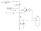
I'm making a battery charge controller for Lead Acid & Sealed Lead Acid batteries using a PIC micro.I just plug an external voltage source (15V DC) & when it is below the set point it will start charge & when it is above the high limit it will turn off the charge.The analog voltage will read by the PIC microcontroller & controls the relay.

I set the Lower set point to 11.3V & Upper Set Point to 14.4V.My battery no load voltage is 12.0V.
The problem is when I hook the battery & plug the external voltage source (15V), the PIC voltage also sees as above 14.4V & stops charging.

How to solve this?
 

Attachments

  • Bat_Charger_PIC.JPG
    Bat_Charger_PIC.JPG
    31.6 KB · Views: 211
For a cyclic charge, you can just leave the 15V connected for however many hours it needs for a full charge, then switch off.

The15V supply needs to be current limited to below the battery maximum charge current - often quite low with small sealed batteries.

Simply reaching full voltage does not mean the battery is full; you need to monitor current as well.

First the voltage goes up, then the current starts to drop.
The battery is only somewhere around half to 2/3 charged at that point.

The battery is considered full when the current drops to a small percentage of its AH capacity - so a good charger will allow you to select the battery size as well.

For standby charge (permanently on charge) you can use 13.8V - so add a couple of diodes in series with the charger.

More complex chargers use both, to give faster charge and less battery degradation; 14.8 until the current drops to a low level, then switch to 13.8 continuously as a float / maintenance charge

You could do that with a second relay that shorts out the diodes.

You could easily add a low value current sense resistor in the battery negative connection, giving a small positive voltage you could read with another PIC ADC input.
Use a series resistor from the shunt to the PIC pin and a small capacitor between ADC and 0V, to filter noise and protect the pin from spikes if the battery leads are shorted! Also a diode back to the PIC power to discharge the filter cap when power is lost.

Don't forget to also subtract that value from the overall voltage measurement, as well as doing the current calculation.

More info on lead-acid charging here:
 
The problem is when I hook the battery & plug the external voltage source (15V), the PIC voltage also sees as above 14.4V & stops charging.
Why is the battery voltage above 14.4V at that point?
 
For a cyclic charge, you can just leave the 15V connected for however many hours it needs for a full charge, then switch off.

The15V supply needs to be current limited to below the battery maximum charge current - often quite low with small sealed batteries.

Simply reaching full voltage does not mean the battery is full; you need to monitor current as well.

First the voltage goes up, then the current starts to drop.
The battery is only somewhere around half to 2/3 charged at that point.

The battery is considered full when the current drops to a small percentage of its AH capacity - so a good charger will allow you to select the battery size as well.

For standby charge (permanently on charge) you can use 13.8V - so add a couple of diodes in series with the charger.

More complex chargers use both, to give faster charge and less battery degradation; 14.8 until the current drops to a low level, then switch to 13.8 continuously as a float / maintenance charge

You could do that with a second relay that shorts out the diodes.

You could easily add a low value current sense resistor in the battery negative connection, giving a small positive voltage you could read with another PIC ADC input.
Use a series resistor from the shunt to the PIC pin and a small capacitor between ADC and 0V, to filter noise and protect the pin from spikes if the battery leads are shorted! Also a diode back to the PIC power to discharge the filter cap when power is lost.

Don't forget to also subtract that value from the overall voltage measurement, as well as doing the current calculation.

More info on lead-acid charging here:
Thanks for the detail reply.I will try to add above as mentioned. Actually I am making a XH-M604 charge controller Module.
 
The voltage across a lead-acid battery will go up very quickly when connected to a high current charger, or if the battery is not fully discharged. It is not proportional to the real state of charge.

And unfortunately that "XH-M604", like many things on the internet, is in reality totally unsuitable for the application it is sold for.

Both lithium and lead-acid cells / batteries need current monitoring to detect full charge, not only voltage detection and on/off control.

Or, a permanent (or many hours) connection to a current limited constant voltage supply, matched to the cell or battery type and capacity - no control needed, then, it naturally drops to trickle or maintenance charge level.


Forget copying that gadget; study the Battery University charging info and make something that works properly!
 
Thinking about it, that battery module may have been originally intended as purely overcharge/overvoltage protection, rather than functional charge control - the features would make sense for that.
It may be that the advert description has been messed up by bad translation.
 
Status
Not open for further replies.

New Articles From Microcontroller Tips

Back
Top