Continue to Site

Welcome to our site!

Electro Tech is an online community (with over 170,000 members) who enjoy talking about and building electronic circuits, projects and gadgets. To participate you need to register. Registration is free. Click here to register now.

  • Welcome to our site! Electro Tech is an online community (with over 170,000 members) who enjoy talking about and building electronic circuits, projects and gadgets. To participate you need to register. Registration is free. Click here to register now.

Batter Charging with MAX712 IC

Status
Not open for further replies.

Jack.Straw

Member
Hello. I am wanting to build a battery charger for a project i'm working on. First, the details:

Charger IC: MAX712 Data Sheet
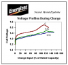
Battery Pack: 6 AA Rayovac Hybrid NiMH 1.2v, 2100mAh
Power Supply: **broken link removed** - 19vDC 3.42A
Intended Charge Rate: 1C using voltage slope detection

There are a number of calculations on the MAX712 datasheet that i'm not 100% sure about. Can anyone confirm these values for me?

**broken link removed**
R1:
R1=(minimum wall-cube voltage - 5v) / 5mA
Is 19v my "minimum" wall-cube voltage since it's a regulated power supply? Assuming the answer is yes: (19v - 5v)/5mA = 2.8k ohm resistor?

Rsense (current sensing resistor):
Ifast=(capacity of battery in mAh)/(charge time in hours)
Ifast=2100mAh/1 hour = 2100

Rsense=.25v/Ifast
Rsense= .25v/2100 = .000119 = .119 ohm resistor?

PNP (Q1)
PDpnp = (maximum wall-cube voltage under load - minimum battery voltage) x (charge current in amps)
The 2N6109 on the datasheet shows a max of 40, but i'm worried about heat. Will a normal TO-220 heatsink like the one below be enough??
**broken link removed**
PGM Settings:
PGM0/PGM1 - Open/Open (6 Cells)
PGM2/PGM3 - Ref/Ref (90 min timeout w/ voltage slope enabled)


Other values (defaults):
Vlimit = Ref
TLO = Batt-
C1 = 1uF
C2 = 0.01uF
C3 = 10uF
R2 = 150 ohm
R3 = 68k ohm
R4 = 22k ohm
D1 = 1N4001


Thank you for any advice you can offer!
-Scott
 
I would have said that 19v input is a little on the high side for charging 6 AA batteries......

That said reducing the input voltage is going to be good for the power dissipation in the 2N6109....which is not operating in a linear mode anyway...

Assuming a fully charged Nimh cell is around 1.2v,then 6 of these will equate to 7.2v..

Having an extra 4volts headroom for the circuit to function correctly I'd say 12v would be sufficient..

In which case R1 would be 1.4k (12-5)/0.005

Rsense stays the same although a preferred value would 0.12 ohms
 
Last edited:
Chippie, thanks for the response. I was goign with that 19v supply because I was having problems finding an inexpensive 12v, 2100ma+ power supply. I don't really need the 1C charge rate though. I found this **broken link removed**.

If i used that one, would I need to do a C/3 charge rate?
 
Last edited:
Sounds better to me.

Leave R1 at 1.4KΩ and increase Rsense to 410mΩ for a charge current of C/2. (600mA).

That way you'll have enough headroom for both, supply voltage and current.

Boncuk
 
Boncuk, thanks for the response. I'm confused by the 600mA part of your response. I was under the impression that C/2 would require 1050mA? (2100mA/2)
 
The 600mA thing has thrown me for a loop. I was thinking C/3 would be my max rate with 2100mAh batteries and a 1A power supply. Am I not understanding something?
 
Charging at 600ma just means the cells wil take longer to charge....3hrs.....


Remember, the cells are 2100mah capacity, charging at 2100ma means they will be charged in an hour(thereabouts)

The 1 amp psu is ok because the load current = the charge current ....600ma in this case
 
Assuming a fully charged Nimh cell is around 1.2v,then 6 of these will equate to 7.2v.
Please do not assume things that are wrong. Look it up.

In Energizer's Ni-MH battery applications manual they show that their AA cell's voltage peaks at 1.55V when it is charged at 1C. Then the total for 6 cells is 9.3V.
 

Attachments

  • Ni-MH charging voltage.PNG
    Ni-MH charging voltage.PNG
    35.7 KB · Views: 994
Please do not assume things that are wrong. Look it up.

In Energizer's Ni-MH battery applications manual they show that their AA cell's voltage peaks at 1.55V when it is charged at 1C. Then the total for 6 cells is 9.3V.

Fair comment...

But I then didnt specify any particular brand of cell.....


Nothing wrong with erring on the side of caution......
 
But I then didnt specify any particular brand of cell.....
The brand doesn't matter. Ni-MH is Ni-MH. They are all the same.

Energizer AA Ni-MH cells are made in Japan by maybe Sanyo. Their 9V Ni-MH battery is made in Germany by whoever.
 
Boncuk, thanks for the response. I'm confused by the 600mA part of your response. I was under the impression that C/2 would require 1050mA? (2100mA/2)

Oops! Number twister. I used 1200mA. :D

Anyway 1050mA will be too much for your small power supply. Go for 80 to 90% load of the rated power.
 
Ok, thanks guys. I ordered a 12v 2A regulated power supply and am going with a C/2 charge rate. I designed and built this layout last night:

**broken link removed**

I hope i got it right. The last thing is to add LED indicators. The datasheet gives this example:

**broken link removed**

Does that mean i should put one LED between R1 and V+ without any other resistors? (i'm used to putting a 1k resistor before my LEDs, but think R1 handles it here?)

Then a 2nd LED between V+ and FASTCHARGE with a 470 ohm resistor preceding it? Why does it say 470 ohm minimum? Should i just use the 1k resistors i have around?

Thanks again for all your help!
-Scott
 
Hello and Happy New Year!

I have built the charger circuit based on the MAX712/MAX713 from this site: Fast, smart and universal NiCd/NiMh battery charger

I've tried with both used and brand new NiMh batteries of 1100 and 1300mAh capacity.
The circuit seems to work fine, except that it SWITCHES OFF after about 15-20 minutes of charging!
(After no more than 5 pictuers, my camera turns off saying that batteries are depleted)
Set to 4 hours max charge time according to datasheet of MAX712. (PGM2, PGM3 = BATT-)
I also tried from 1 cell to 4 cells, (+ dip switches changed) Rsense 0.6 and 1 Ohm, Rshunt 0,6K and 1,4K Ohms with same results.
Charging currents are fine. (250mA / 1 Ohm, 415mA / 0,6 Ohm)

What could be wrong? What should I check?

Could be that I am using a BD 434 on a decent heat sink? By touch it's slightly warm, I'd say around 45-50 deg C, so it handles that current easily.

Thanks.
 
Last edited:
I can see where you connect PG3 on your cirucit?

thanks for answer,
Ok, thanks guys. I ordered a 12v 2A regulated power supply and am going with a C/2 charge rate. I designed and built this layout last night:

134-charger.jpg


I hope i got it right. The last thing is to add LED indicators. The datasheet gives this example:

135-LED.jpg


Does that mean i should put one LED between R1 and V+ without any other resistors? (i'm used to putting a 1k resistor before my LEDs, but think R1 handles it here?)

Then a 2nd LED between V+ and FASTCHARGE with a 470 ohm resistor preceding it? Why does it say 470 ohm minimum? Should i just use the 1k resistors i have around?

Thanks again for all your help!
-Scott
 
the resistor values should be chosen so that the current throught the leds is not exceeded...

Check the operating data for the leds you have selected...Typical value is 20mA
 
Last edited:
Status
Not open for further replies.

Latest threads

New Articles From Microcontroller Tips

Back
Top