voodoo5293
New Member
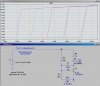
I want to build this battery charger:
**broken link removed**
To charge this battery:
Model: YTX5L-BS
I want to limit the current to about .75A. So I guess that means I need to use a .8 ohm resistor for the resistor that it doesn't have a value for, unless I am mistaken. I also want to add an LED that will light up to indicate the battery is fully charged. I have no idea how to go about doing that. Also, what voltage should I set it to charge at? 13.8? One other thing, what does the transistor do in this circuit? I have seen many similar circuits using the same LM317, and none of them used any transistors. Thanks in advance for any help.
Last edited:
")