Continue to Site

Welcome to our site!

Electro Tech is an online community (with over 170,000 members) who enjoy talking about and building electronic circuits, projects and gadgets. To participate you need to register. Registration is free. Click here to register now.

  • Welcome to our site! Electro Tech is an online community (with over 170,000 members) who enjoy talking about and building electronic circuits, projects and gadgets. To participate you need to register. Registration is free. Click here to register now.

BasicX24 and ULN2803 combination..

Status
Not open for further replies.

ize

New Member
Hi, I'm in a project in which we are trying to control four vibrators (regular pancake mobilephone things) with a BasicX24-chip and a ULN2803 as a driver.

Now, have I got this right?

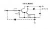
The control pins on the BX are 7-10, which are connected to pin 11-14 on the ULN. Is it correct to pick out current to the vibrators at pin 5-8 at the ULN? Ground are connected to pin 9 and current at pin 1.

It is not working.. as you might have figured out ;) The question is if I've done a poor job programming or connecting it ..


Very grateful for all help..
 
I believe you have your connections turned around. Your BX should connect to pins 5-8 and the motor 11-14. Also there are some clamp diodes included for protection.

Also remember that it is acts as "inverter" as well. Check out the attached schematic of the representative circuit for each "driver". Also remember that they are open collector outputs, meaning that they will only be able to "supply" a ground connection, if you want a "high" connection you will need a pullup resistor.

"The eight NPN Darlington connected transistors in this family of arrays are ideally suited for interfacing between low logic level digital circuitry (such as TTL, CMOS or PMOS/NMOS)"............................................ "All devices feature open–collector outputs and free wheeling clamp diodes for transient suppression."

Check the **broken link removed**
Ivancho[/quote]
 

Attachments

  • ULN2803_diagram.jpg
    ULN2803_diagram.jpg
    7.3 KB · Views: 1,093
Thanx alot! I'll try that and get back to you on the progress..

and for the schematics..I'm such a newbie that reading a datasheet poses a big problem, I don't know the symbols very well :oops: and I have no electronic experience what so ever..

" Also remember that they are open collector outputs, meaning that they will only be able to "supply" a ground connection"

Does that mean that a ULN really isn't a driver(adding current to the vibrators) but a ground controller(current to vibrators is supplied elsewhere and ground is supplied by the ULN to form a closed circuit )?
 
Since it is a vibrator I am guessing it will only rotate one way. And if the vibrator does not use more than 500mA then you will be OK useing that cihp.

So what you want to do is connect the positive side of the vibrator to the positive side of the battery. Then the other side of the vibrator to one of the output pins 11-18. Now by controlling your input you are going to be able to allow current to flow thru the vibrator, or not.

Don't forget to connect the Pin9 to ground and if you would like connect the Pin10 to +V (battery positive side) for safety reasons.

Ivancho
 
Status
Not open for further replies.

Latest threads

New Articles From Microcontroller Tips

Back
Top