Continue to Site

Welcome to our site!

Electro Tech is an online community (with over 170,000 members) who enjoy talking about and building electronic circuits, projects and gadgets. To participate you need to register. Registration is free. Click here to register now.

  • Welcome to our site! Electro Tech is an online community (with over 170,000 members) who enjoy talking about and building electronic circuits, projects and gadgets. To participate you need to register. Registration is free. Click here to register now.

Basic questions about MOSFETS, Gate Drivers and Diodes

Status
Not open for further replies.

kitstudent

New Member
Hi!

I have some general question about electronic components. I don't understand how or when they should be used, maybe someone can explain :)

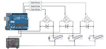
Gatedriver and mosfet:
- when do I actually need a Gate Driver? As far as I understand it is used if the control device's output current or voltage is not high enough For (for example) the control of the mosfet with PWM from an arduino. So what and how excatly does the Gate Driver do? Increase current or voltage to the amount the mosfet requires?

Diodes:
- first of all whats the difference between flyback diode and TVS diode? I understand that both are used to protect from voltage spiked but when do I use a TVS and when a flyback?
- sometimes I see that a resistance is parallel to the device to be protected instead of a diode. Why is that so? A resistance would also decrease current right?

Thanks in advance!!
 
Power MOSFETs have [relatively] very high gate capacitance.

For simple on-off switching & moderate loads, that probably does not matter; the FET may take a millisecond or a few milliseconds to change between fully on and completely off.
During the part on / part off stage, it will dissipate rather more power than in the on or off state.

As long as that burst of power (and heat) is not excessive, it's not a problem.

But, if you are trying to switch a MOSFET very quickly & repeatedly like with PWM or in a switch mode PSU, or with high loads, the change between on and off must be as short as possible, to properly control the load and minimise the power loss and FET heating.

That's when high current gate drivers come in, that can often give current of an amp or two, to charge and discharge the gate as fast as possible.


A "Flyback" or "flywheel diode" is just a type of use of a general purpose or fast recovery diode - when it's used with an inductive load to prevent high voltage spikes damaging things or causing electrical interference; or when deliberately to capture the energy from the inductor, as in a power supply or converter.

A TVS is rather like a zener diode but faster, it will conduct and dissipate the energy from an overvoltage spike.
(Voltage-dependant resistors, aka VDRs or Zenamics are another type of device that does a similar kind of thing).

A resistor can be used across an inductor to limit the back EMF spike, as it will draw current in proportion to the voltage so limit it; eg. if it takes 1/10th the inductor current at normal voltage, it will take the full current at 10x voltage so the spike cannot be any higher than that.

The back EMF spike from even such as a small 12V relay can easily reach 500 - 1000V, so even limiting it to a few times working voltage can help prevent the switch or contacts controlling it from arcing or being burned.

Resistors across large coils like magnetic clutches were common in older machines, before semiconductor devices were developed & are sometimes still used, as they damp the circulating current far faster than a flywheel diode, allowing the device to switch off more quickly.
Thanks!!
So if I use a mosfet with high frequency PWM, would you rather recommend using a TVS as protection?
And if I have want to heat a wire via joule heating, would you rather recomment a TVS or a Flyback diode for the wire?
 
It is hard to imagine how a TVS would help a PWM circuit, but without seeing your proposed circuit we would only be guessing.

Wires rarely need transient voltage protection - they melt you used the wrong wire. Only is your wire had much inductance or was very long (same thing) would there be any transient pulses to worry about. Again, if you post your circuits it can help get you more definite answers.
 
Thanks!!
So if I use a mosfet with high frequency PWM, would you rather recommend using a TVS as protection?
And if I have want to heat a wire via joule heating, would you rather recomment a TVS or a Flyback diode for the wire?
If you mean resistive heating, then no load protection (other than circuit fusing) is needed - heating elements are non-inductive loads so no back emf problems, as DC says.
 
It is hard to imagine how a TVS would help a PWM circuit, but without seeing your proposed circuit we would only be guessing.

Wires rarely need transient voltage protection - they melt you used the wrong wire. Only is your wire had much inductance or was very long (same thing) would there be any transient pulses to worry about. Again, if you post your circuits it can help get you more definite answers.
the circuit should look like this and I am not sure wether I should use a flyback diode or TVS for the mosfet. Same goes for the wire itself. The wire should be heated by joule heating.

the voltage should be around 5V and the current needed by the wire around 3-6A
 

Attachments

  • circuit 2.JPG
    circuit 2.JPG
    117.3 KB · Views: 191
None are needed.

What is the response time of the heating elements? If it's relatively slow you should be able to use very low frequency PWM, just a few Hz, and may not even need any gate drivers as long as the FETs are logic-level devices.

If that's OK, just add a fairly low value series resistor from the Arduino outputs to the FET gates to limit current, eg. 100 Ohms or so, and a high value resistor between gate and source at each device to ensure the remain off if a connection is lost - 100K or more.
 
- sometimes I see that a resistance is parallel to the device to be protected instead of a diode. Why is that so? A resistance would also decrease current right?
Relays often have a resistor in parallel to the coil, to limit the voltage created when the supply is turned off. As rjenkinsgb said, having a resistor of 10 times the coil resistance will lead to a voltage spike that is at most 10 times the supply voltage, so as long as the transistor is rated to 10 times the supply voltage, it will switch the relay coil fine.

The resistor will increase the current, not decrease it. That is because it is in parallel with the coil.

Resistors are used because they reduce the coil current much faster than a diode would. If the current in a relay coil is turned off too slowly, the contacts will be pulled apart slowly, and that can cause the contacts to be damaged, on some types of load.

Often the resistors are fitted within the relay housing. The connections to the coil can be either way round. If a diode inside the relay housing is used, the relay coil has to be connected the correct way round.
 
The wire should heat up very fast (within a few miliseconds) and the frequency of PWM is about 10 Hz.


None are needed.

What is the response time of the heating elements? If it's relatively slow you should be able to use very low frequency PWM, just a few Hz, and may not even need any gate drivers as long as the FETs are logic-level devices.

If that's OK, just add a fairly low value series resistor from the Arduino outputs to the FET gates to limit current, eg. 100 Ohms or so, and a high value resistor between gate and source at each device to ensure the remain off if a connection is lost - 100K or mt
 
The wire should heat up very fast (within a few miliseconds) and the frequency of PWM is about 10 Hz.
PWM is often fast enough that whatever is being controlled doesn't respond. In this case, the wires will be getting hot and cold 10 times a second. Is that what you want?

If you want to keep the wires at a steady temperature, and the response time is a few ms, you should have PWM that is about 1 kHz or faster.
 
I built a hot wire cutter a while ago and used PWM at 10Hz to control it. Basically x mS out of every 100mS was the percentage on. I doubt you'll be able to tell that it's not a constant temperature.

Mike.
 
the circuit should look like this and I am not sure wether I should use a flyback diode or TVS for the mosfet. Same goes for the wire itself. The wire should be heated by joule heating.

the voltage should be around 5V and the current needed by the wire around 3-6A
I don't see why you would think you need either unless that heating wire has a lot of inductance. For peace of mind, consider using a fast diode (Schottky is fine) with a peak current rating as high as the peak current in the wire.
 
Status
Not open for further replies.

Latest threads

New Articles From Microcontroller Tips

Back
Top