mstechca
New Member
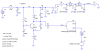
I was again tinkering with my superregen (a.k.a. Audioguru's "TOY" :lol: )
and I notice that nigel's information about the capacitor connected between the NPN's base and ground seems accurate.
I read that selectivity is supposed to suffer from incorrect <quench frequency>:<incoming frequency> ratio.
selectivity and bandwidth do relate to each other in opposite ways. wouldn't you agree?
I was wondering, could I calculate bandwidth based on the incoming frequency and the quench frequency?
if so, is there a simple equation for it?
Maybe this is the reason why I can pick up a TV signal when I adjust the quench oscillator capacitor to one value, and I can't pick up the same signal when I adjust the capacitor to another value.
") The quench (squegg) frequency is a complex situation. As the transistor starts to oscillate (RF), it draws more current. This brings down the voltage on the collector. The base current, being derived from the collector voltage,starts to decrease, but there is a lag due to the RC time constant of the base bias network. eventually, the base current is too low to sustain oscillation, so the collector voltage rises rapidly. However, there is a lag in the increase in base current due to the base bias network time constant, ... I think you get the idea.
The quench (squegg) frequency is a complex situation. As the transistor starts to oscillate (RF), it draws more current. This brings down the voltage on the collector. The base current, being derived from the collector voltage,starts to decrease, but there is a lag due to the RC time constant of the base bias network. eventually, the base current is too low to sustain oscillation, so the collector voltage rises rapidly. However, there is a lag in the increase in base current due to the base bias network time constant, ... I think you get the idea.