Continue to Site

Welcome to our site!

Electro Tech is an online community (with over 170,000 members) who enjoy talking about and building electronic circuits, projects and gadgets. To participate you need to register. Registration is free. Click here to register now.

  • Welcome to our site! Electro Tech is an online community (with over 170,000 members) who enjoy talking about and building electronic circuits, projects and gadgets. To participate you need to register. Registration is free. Click here to register now.

bandwidth etc.

Status
Not open for further replies.
PG,

Let's step through your previous post to try and clear some confusion.

... I had in mind that information signal's frequency modifies the frequency of the carrier. That's totally wrong ...
I don't know if it's totally wrong. Right and wrong are like black and white, which are abstractions. The world is color and shades of grey. We have to be careful when we use words to express technical facts. The words are an attempt to describe and understand, but they are not always accurate. For AM, the carrier frequency is in some sense not modified by the signal because it is still present in the spectrum. The sidebands are a combination of the carrier and signal. Certainly something has been modified, but whether the carrier frequency has or has not been modified is a viewpoint, not a fact. Of course, if you define what "modified" means more clearly, then we can say something with more confidence. For FM, we are directly changing the frequency actively, so we might say something different here. In some sense the carrier frequency is modified. But, these are just words, and the mathematics provides a better description than words.

Look at the mathematics (which is much more cumbersome) of FM here **broken link removed** . Here you see multiple sidebands are generated. The carrier is there and then many sidebands (actually an infinite number of them). Well, can't we argue that the carrier is still there unmodified? At least partially? It's just words without meaning if we don't define what we mean clearly.

...Suppose we want to transmit baseband voice signal which has bandwidth of 3kHz (300-3300Hz) using a carrier of 700kHz. Here, we can say 700kHz is center frequency, fc, of the carrier, and (300+3300)/2=1800Hz=1.8kHz is fc of the baseband signal. The bandwidth of the carrier is going to be (700-1.8)kHz to (700+1.8)kHz or 698.2kHz to 701.8kHz with 700kHz as the center frequency. Q1: Do I have the information correct up to this point?

As we mentioned above this is not the correct viewpoint. I think you understand this now from the above discussions.

...I believe this is the part where my confusion lies. In frequency modulation amplitude of the information signal modifies the frequency of a carrier signal. It means that even when the two information signals are different but have the same amplitude then they would modulate the carrier the same way. Let me put it differently. If you say the letter 'k' and 'q' in such a way that they both create same pressure gradient (or, amplitude) then both of them modifies the carrier's frequency the same way, and hence two different kinds of signals (letter 'k' and 'q') get mixed up. Q2: Is this possible? If not, then why not? Why can't two different signals give rise to same amplitude?

I'm not sure i understand you completely. Whether the signal information is encoded with amplitude or frequency should not matter. As long as we demodulate by the reverse process and recover the original signal, we should understand everything perfectly, as if nothing ever happened to the signal.

...I understand that convolution in time domain becomes multiplication in frequency domain, i.e. convolution of f(t) and g(t) becomes F(s)*G(s) in frequency domain, and convolution in frequency domain becomes multiplication in time domain, i.e. convolution of F(s) and G(s) becomes f(t)*g(t) in time domain. But I don't see the point where you say "This is why the frequencies add to give the upper and lower side bands". Q3: What are you trying to point out? Could you please clarify it?

I think you may understand this now from the above posts. But, basically, convolution of impulses creates an addition/subtraction of frequencies. This is due to the way the convolution integral works, with its "sifting" property.

I'm also trying to point out that visualization of modulation can be much easier in the frequency domain, once you put the effort into understanding from this point of view.

This is a little bit ironic because Fourier analysis is a linear theory and modulation is a nonlinear operation. But, it is the multiplication/convolution relation in the time/frequency domains that makes this work.

By the way, the general rule is that linear systems don't generate new frequencies and it requires nonlinearity to modify frequencies.

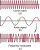
...This is how I see it. Suppose we have a information signal f(t)=cos(2∏ft) and carrier signal g(t)=cos(2*∏*50*t). In frequency modulation the factor "50" of the carrier is modified by amplitude of the information signal as shown here.

Yes, with FM it is modified. The above reference I gave shows how it is modified. You generate a carrier frequency and an infinite number of sidebands. That's still not too much different than AM where we get a carrier and one upper sideband and one lower sideband.

Note, that when we transmit, we dont' want to send out an infinite number of sidebands that will interfere with other channels. So, you should expect that there is a filtering operation that we have not yet talked about.

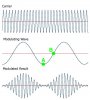
...Now I turn to amplitude modulation. In amplitude modulation, the amplitude of the carrier is modified by the amplitude of an information signal and the frequency of the carrier remains constant. This means that in case of amplitude modulation, we don't need bandwidth because frequency of the carrier always remains constant, i.e. if it's 500kHz then it's always going to remain at this value and hence no upper and lower frequency limits and therefore no bandwidth. Q4: Where do I have it wrong?

I hope now you see where you have it wrong. You have mentally used words in place of math. As I mentioned at the top of this post, this is dangerous thinking if you are not careful. There are more similarities than differences with AM and FM. In both cases, we get a carrier and sidebands. All sidebands contain the baseband information and each one alone could be used to recover the original baseband signal.

A bottom line fact is that no bandwidth implies no information content, and information and bandwidth are intimately tied together.
 
Last edited:
Thank you very much for the help and your time, Steve. It was really nice and kind of you.

I need to clarify three important points before I stop pursuing this topic in critical detail because many of the confusions will get cleared with time and as I get into mathematical details.

Q1:
Though you have commented on physical interpretation of negative frequency in post #10 (last paragraph), I'm still not satisfied. I understand your point where you said, "Ultimately, the sign relates to rotation (clockwise is negative and counter-clockwise is positive) whether it's a real rotation (like with motors)...". I understand the concept of negative frequency in context of a motor where if there is clockwise rotation then it means negative cycles and hence negative frequency. Can a **broken link removed** have negative frequency? When can it have negative cycles? Likewise, assuming water waves can be represented by pure sinusoidal waves model, when can water waves have negative frequency? You have also said that we can think of positive and negative frequencies representing the same thing. I'm sorry but I find it hard to accept. It's just like saying that "-5" and "+5" numbers stand for the same thing.


Q2:
Which of the points, A or B, of information signal, amplitude modulation and frequency modulation, will leave the carrier unaffected?


Q3:
In amplitude modulation, amplitude of an information signal is used to modulate the amplitude of the carrier.

So, we have a carrier at frequency ωc and a signal at frequency ωs, which are simple cosine functions, and we multiply them as follows.

[latex]V_m=V_c \cdot V_s=A_c \cdot \cos(\omega_c\cdot t) \cdot A_s \cdot \cos(\omega_s \cdot t) [/latex]

cs_am_definition-jpg.75140


Thanks a lot for the help.

Regards
PG
 

Attachments

  • cs_AMMOD.jpg
    cs_AMMOD.jpg
    60.5 KB · Views: 330
  • cs_fm.jpg
    cs_fm.jpg
    114.1 KB · Views: 332
  • cs_am_definition.jpg
    cs_am_definition.jpg
    57.4 KB · Views: 519
PG,

Q1: You'll have to come to grips with this on your own terms, as we all do eventually. I know the explanation is unsatisfactory. We are naturally biased to prefer positive over negative. When your employer pays you 5 dollars, it is -5 to him and +5 to you. Many things are relative to your point of view.

The bottom line is that we use the math with positive and negative frequency because we resort to using complex numbers to simplify the math. Once, we are in the complex domain, frequency becomes a rotation into the imaginary direction, and positive and negative have different (although symmetrical) effects. When we translate back to the real world, either positive or negative gives us the information we need. You saw how we can use real numbers to show how AM gives an upper and lower sideband, then we did it in the frequency domain with positive and negative frequencies. It's just math, and we have to get used to what the math tells us. Historically, the concept of the number 0, negative numbers and imaginary numbers have given people a lot of headaches. You are not the first to fight with this.

Q2: I would tend to think that point B leaves it unmodified, but it could also depend on implementation.

Q3: JimB pointed out that my presentation would be more confusing and he was right. Did you try to do the analysis as he recommended (and as I agreed you should do). You need to do the math to really come to grips with this. Us showing the math is only going to get you so far. You need to work it out yourself for it to sink in.

I was just showing a very special case of modulation which is pure multiplication of signals. The reason I did this was to simplify the math and show that multiplication in the time domain is convolution in the frequency domain. In this way you could see the frequency shifting. Most modulation is not a pure multiplication of signals, and then you are forced to work it out in the time domain. Did you trace the math for FM from the reference I provided. This is also not simple multiplication.
 
Last edited:
Thanks a lot, Steve.

steveB said:
Did you try to do the analysis as he recommended (and as I agreed you should do)....Did you trace the math for FM from the reference I provided.

Sorry. I didn't. But I intend to go though all the details after two or three days. So, until then I think it's better to suspend the discussion at this point. Once again, thanks.

Regards
PG
 
Hi

My apologies for getting back to this discussion a little later than promised. This does not mean I had forgotten about it. I had it in mind and that's the reason I didn't post any new query here. Actually I was working on several other things. I was also reading about several types of amplitude modulation and was supposed by my instructor to have an understanding of them . So, as you say, first things first, I thought it's better to first go through the topics at superficial level and then gradually I can work on my conceptual understanding of the concept. Sorry for the misunderstanding.

This is an extract from a text I'm working on. I hope it's correct. If not correct then kindly guide me where I have it wrong. Thank you.

Regards
PG
 

Attachments

  • CS_DSB.jpg
    CS_DSB.jpg
    235.1 KB · Views: 342
In post #25, I believe you are correctly doing the case that JimB recommended.

In post #26 ...

For Q1, I thing the block diagram is not quite right but is intended for schematic purposes only. Your version is also OK for schematic illustration, but also does not exactly correspond to the math in post #25.

For Q2, i think what you did in post #25 is fine and better than your new method. It is all a matter of how you decide to set it up, so I can't say it's wrong. Consider that the units in your new version dont' match, but this is not a real problem since you can scale voltages as needed. But this is exactly why your first first is better, the scaling is M=Vm/Vc and provides a nice indication of the modulation factor.
 
Q1 Yes your drawing is better, maybe. It better represents what is happening in that first line of mathematics.

Q2 I think that missing out Vc if effectively stating that the unmodulated carrier has a value of 1.
If you were looking for an absolute value of the modulated carrier at any instant then yes you would need to account for Vc.

All this mathematics is all very well, but does the school/college have any practical exercises with a modulator and some test equipment?
If there was it may start to make more sense.

JimB
 
Thank you, Steve, Jim.

Could you please help me with these follow-on queries? Thanks.

Regards
PG
 

Attachments

  • cs_am4.jpg
    cs_am4.jpg
    716.8 KB · Views: 329
Q1: This is not my area of expertise, but I think you would try to avoid divider circuits generally and would not need them. Amplification, shifting and multiplying (or other nonlinear modulation method) should be enough to get something working.

Q2: The math and the implementation are two entirely different things. I think trying to discuss this too much without real implementations and circuits is counterproductive and confusing. The math always generates the principles for our designs. Then, we need to be creative and figure out how to actually implement the math. Of course, this is old technology, so you dont' need to invent anything. Simply study what has been done. For example, look up and make a simple AM modulator with a transistor.

I think JimB was hinting at this basic point in his last post.

Q3: The USB and LSB contain the same information about the baseband signal. That is the main point. Either side band can be demodulated to obtain the baseband information. Hence, removing 1 sideband allows better use of available bandwidth without loss of information in principle. However, talking too much about this without also discussing demodulation methods might be confusing. For now, the main point is about information content and both sidebands contain exactly the same information.
 
This is being analysed to absurdity.
Theory without practice is just waffle and conjecture in my highly biased opinion.

In my younger days I blew my mind trying to understand the operation of transistor circuits (I had already a reasonable understanding of valves).
I would start reading books which went on about electrons and holes, had diagrams of common base transistor circuits with at least two batteries and no resistors. It still hurts to think about it 50 years later.

Amplitude modulation has worked very well for over 100 years.
As Steve has said, the diagrams used here bear no relation to a practical circuit.

The upper sideband and the lower sideband of an AM signal contain exactly the same information. Fact.
What may be confusing you, as we increase to modulating frequency, the upper side frequency increases and the lower side frequency decreases.
If the modulating frequency is 2kHz, the USF is 2kHz above the carrier and the LSF is 2 kHz below the carrier.
Listen to the signal with an AM receiver you will hear a 2kHz tone.
Listen to the signal with a Single Side Band (SSB) receiver set to Upper Side Band (USB) and you will hear a 2kHz tone.
Now if you switch the SSB receiver to Lower Side Band (LSB) you will hear a 2kHz tone, exactly the same as on USB.
(Assuming that the tuning is correct).

JimB
 
Thanks a lot, Steve, JimB.

Could you please give this text a look? Please let me know if there is something grossly wrong and could potentially lead to further misunderstanding in future. Thank you very much.

The order of the links provided under References is opposite to the flow of text.

Regards
PG


References:
1: **broken link removed**
2: http://books.google.com/books?id=L8...6AEwAQ#v=onepage&q=vestigial sideband&f=false
3: http://encyclopedia2.thefreedictionary.com/QAM
4: **broken link removed**
5: http://www.hamuniverse.com/ssbinformation.html
6: **broken link removed**
7: http://books.google.com/books?id=C1...QXO2oDACw&ved=0CCoQ6AEwAQ#v=onepage&q&f=false
8: https://www.electro-tech-online.com/custompdfs/2013/08/Chap3-Amplitude20modulation.pdf
9: http://en.wikipedia.org/wiki/Impedance_matching
10: http://en.wikipedia.org/wiki/Single-sideband_modulation
11: http://iitg.vlab.co.in/?sub=59&brch=163&sim=259&cnt=359
12: http://books.google.com/books?id=L5...F-4HIBA&ved=0CDsQ6AEwATgK#v=onepage&q&f=false
 
Suppose the green dot represents one of the sine waves present in the spectrum of the modulating signal.

Let’s say it’s frequency is 10 Hz and that of the carrier is 1 kHz. A sine or cosine wave always alternates

between positive and negative cycles. Also don’t forget that Fourier series or transform always represents a

given signal using sinusoids. In amplitude modulation (AM) the amplitude of a carrier signal is controlled by a

modulating signal. As the modulating sine wave’s frequency is 10 Hz and that of the carrier is 1 kHz so LSB

is 990 Hz and USB is 1010 Hz. We can see there is a change of 10 Hz below and above the carrier’s

frequency. What’s the reason for this symmetry? Let’s focus on a single cycle of the given sine wave.

The positive half-cycle affects the carrier’s amplitude in such a way that its effect is compensated by a sine

wave with frequency of 1010 Hz. Now the negative half-cycle which is similar to the positive except that it has

negative value affects the carrier wave’s amplitude in such a way that its effect is balanced by a sine wave

of frequency 990 Hz. In other words, we can say postive half-cycle pushes the frequency of the carrier toward

the right while the negative half-cycle pulls the frequency of the carrier toward the left. The important thing

Total nonsense.
There may be more but this is glaringly wrong.

JimB
 
JimB is sharper than I. :) He can read that and know it's wrong. I can only read it and have no clue what they are trying to say there.
 
Status
Not open for further replies.

Latest threads

Back
Top