Continue to Site

Welcome to our site!

Electro Tech is an online community (with over 170,000 members) who enjoy talking about and building electronic circuits, projects and gadgets. To participate you need to register. Registration is free. Click here to register now.

  • Welcome to our site! Electro Tech is an online community (with over 170,000 members) who enjoy talking about and building electronic circuits, projects and gadgets. To participate you need to register. Registration is free. Click here to register now.

bandpass in TDA7293 monoblock

Status
Not open for further replies.
Hello,

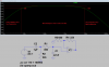
what I am trying to do, cut off unwanted frequencies from a bunch of TDA 7293 monoblocks. TT is doing upto 240 Hz, MT is meant to do 240-2100Hz and HT the rest. So I simulated it, see pictures. Is this a good plan? As within limits one can change the values from the data sheet. And the amplification remains the same.

Cheers,

case.
 

Attachments

  • TT bandpass.gif
    TT bandpass.gif
    39.4 KB · Views: 148
  • MT bandpass.gif
    MT bandpass.gif
    38.4 KB · Views: 160
  • HT bandpass.gif
    HT bandpass.gif
    40.6 KB · Views: 134
Your RC lowpass and highpass filters have a very gradual cutoff of only -6dB per octave.
The value of R3 is so low that the input impedance at high frequencies is extremely low.
 
the 680 ohm for R3 is from ST, its R2 in their schematic. I am not using this as crossovers, that is coming before. My plan is just avoid amplifying unwanted noise. How far can the TDA7293 go, MHz?
 

Attachments

  • tda7293 reference.gif
    tda7293 reference.gif
    54.6 KB · Views: 288
Nobody speaks using only low frequency vowels. The important consonant sounds in speech reach 14kHz and you are reducing them.

Your R2 is only 390 ohms and it feeds your C2 that is huge at 0.1uF. Then if the source impedance is very low they gradually cut frequencies above 4.1kHz. If R2 is 3.9k and C2 is 0.01uF then the cutoff will be the same but the input impedance can be 10 times higher.
Audio goes to 20kHz and audio amplifiers go maybe to 100kHz so that there is no attenuation of 20kHz.
Since the slew rate of the TDA7293 is 15V/μs, I think with its gain at 33 times then its frequency response is -3dB at about 60kHz, and zero gain above 5MHz.
 
Its an active amp, so I am making 3 versions, one for the bass, one for mid and one for high. So if the bass cuts out at 1kHz, mid at 4 kHz and high at 18kHz, its ok. Would help if they pick up noises or oscillate. I think I will make the gain lower.
 
Your filters are simple RC passive ones, not multi-order active filters. Their filtering effect is very small. Their input impedance is so low that you might need a power amplifier to drive them. An active filter has at least two orders and has negative feedback around it so its cutoff is sharp. An active filter filters well and has a high input impedance so that anything will drive it.

Your Bode Plotter is useless without having its horizontal lines showing dBs and its vertical lines showing frequencies.
How do you get a bass cutoff at 1kHz? If the source impedance is zero then the cutoff frequency (-3dB) for the 390 ohms and 100nF cap is 4.1kHz and is reduced if the source has some impedance.
The lows have a cutoff frequency in the bandpass filter for 1μF cap and 22k at 7.3Hz and its highs have a cutoff frequency for the 390 ohms and 47nF cap at 8.7kHz.
The lows have a cutoff frequency in the highpass filter for the 0.39μF cap and 22k at 18.7Hz and the highs have a cutoff for the 390 ohms and the 8nF cap at 51.3kHz which is crazy.

Here is a simulation of your mids bandpass filter if it is driven from an amplifier that has zero impedance:
 

Attachments

  • mids bandpass filter.png
    mids bandpass filter.png
    29.5 KB · Views: 150
I renamed some parts to they tie in with the schematic from ST and there are horizontal and vertical lines.
https://www.ti.com/lit/ds/symlink/opa134.pdf
has the output impedance for the OPA 134. But after that comes a 22kohm poti to adjust the level for the individual drivers
 

Attachments

  • MT bandpass sweep.gif
    MT bandpass sweep.gif
    42 KB · Views: 144
  • HT bandpass sweep.gif
    HT bandpass sweep.gif
    37.3 KB · Views: 114
  • TT bandpass sweep.gif
    TT bandpass sweep.gif
    45 KB · Views: 120
You do not show an OPA134 opamp. Instead you show the high voltages and resistances of a TDA7293 power amplifier. Were is the OPA134 and what is its function?
You cannot add a level control pot to the extremely low impedance inputs of your filters because the resistance of the pot will add to the resistances in your filters and mess up the frequency responses.

Did you notice that my frequency response graph shows the actual gain of from 0dB to +33dB but your graphs show ranges of 35dB, 45dB and 130dB?
 
The OP134 is the active filter that comes before. There is a 12dB/octave active filter. So I would have to put another opamp into my simulation, then the poti say 11kOhm.
Below R2_ST the 680 ohm, there are 2 elcos. Their value changes things as well, but more at the low end.
 

Attachments

  • HT bandpass sweep 2.gif
    HT bandpass sweep 2.gif
    42.6 KB · Views: 135
  • MT bandpass sweep 2.gif
    MT bandpass sweep 2.gif
    45.1 KB · Views: 118
  • TT bandpass sweep 2.gif
    TT bandpass sweep 2.gif
    44.9 KB · Views: 143
You continue to show the same horrible extremely low input impedance filters but do not show where the "poti" and OPA134 are connected to them. It sounds like the "poti" feeds the inputs of the horrible filters and messes up their frequency responses.
The two 39μF capacitors on series and 680 ohm resistor cause another cutoff at 6Hz or 12Hz that does not affect the audio.

I do not understand why you are filtering the 12dB/octave active filter.
 
yes, there are problems, depending on the potentiometer settings. Why I am filtering it? Got problems with interference, if I can get rid of some noise this way... Plus wit amps muted, the transformer draws 2W, not muted 16W. But all there is, is some buzzing noise. So it must be doing something crazy. Oscillating at high frequencies?
 

Attachments

  • MT bandpass sweep 3.gif
    MT bandpass sweep 3.gif
    55.7 KB · Views: 139
Interference? Solderless breadboard construction with millions of jumper wires and rows of contacts acting as antennas? The capacitance between all the wires and rows of contacts on a solderless breadboard causing oscillation?

1) Your "volume control" is a rheostat (a variable resistor) instead of a voltage divider.
2) Your volume control is in the wrong place, it should be at the input of the opamp or amplifier, not at the output since its resistance adds to the resistance of R3.
3) Your Sallen-Key lowpass filter is a droopy Bessel instead of a sharp Butterworth type.
 

Attachments

  • lowpass filter.png
    lowpass filter.png
    43.3 KB · Views: 111

Attachments

  • MT bandpass sweep 4.gif
    MT bandpass sweep 4.gif
    52.6 KB · Views: 110
  • MT bandpass sweep 5.gif
    MT bandpass sweep 5.gif
    47.9 KB · Views: 109
Last edited:
Your complex schematic is impossible to read since its text is splattered all over its parts.
Your new Butterworth second-order lowpass filter has a sharp cutoff at about 3.2kHz.
Your RC filter is a mess with an extremely low input impedance to high frequencies. Thank you for putting the volume control in the correct location on the "sweep 5".
Your graphs are meaningless since they have a huge dB range and the two traces not labelled.

Audio cables are supposed to be shielded then the shield blocks interference.
 
the audio cables are shielded and really short, still got interference. Could try twisted and shielded. Teisted did not work. Or connect the shield via the R and C as in the image from that
**broken link removed** page

Which RC filter, this one?
BBHumRFIFigure6.jpg


the crossover image I just posted to show, its not just on breadboard. Its existing on PCB.

https://www.bluejeanscable.com/articles/humrejection.htm I check, got some ot that hanging around
 
Last edited:
Status
Not open for further replies.

Latest threads

New Articles From Microcontroller Tips

Back
Top