Continue to Site

Welcome to our site!

Electro Tech is an online community (with over 170,000 members) who enjoy talking about and building electronic circuits, projects and gadgets. To participate you need to register. Registration is free. Click here to register now.

  • Welcome to our site! Electro Tech is an online community (with over 170,000 members) who enjoy talking about and building electronic circuits, projects and gadgets. To participate you need to register. Registration is free. Click here to register now.

Band Pass Filter

Status
Not open for further replies.

Gandledorf

New Member
I'm trying to recall my analog electronics, and don't know if I have this right, so if someone could help me, I'd appreciate it. As I remember, a band pass filter has the basic form as follows:

**broken link removed**

And passes a frequency determined as follows:

fr = 1 / 2 * pi * sqrt(L1 * C1)

However I don't remember how to choose R1 for this circuit.

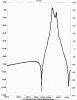
Assuming I want to bandpass the frequency 56kHz, using an 820uH inductor, and a 10pF ceramic capacitor, I get a pass frequency of 55.579kHz, would this be good enough?
 
Analogue Bandpass filter

What you have drawn is a tuned circuit with a resistor in parallel. The resistor will broaden the band but reduce the Q. I don't know why the resistor is connected to Vcc as there is no point in this and it could saturate the inductor. It is a bit complicated to explain here, so send me an email explaing in more detail of what you are trying to do and I'll help
 
Taking ljcox 's advice, I put together an active band pass filter instead. Let me know if this is right... I derived this from discoverciruits.com

**broken link removed**

Given a lower frequency of 54k, an upper frequency of 58k,

Center frequency = sqrt(54000 * 58000) = 55964.27

Band Width = 4000

Q = cf/bw = 13.99

R1 = Q / (G * C * 2 * Pi * cf)
R2 = Q / ((2 * Q^2) - G) * 2C * Pi * cf)
R3 = 2Q / (2C * Pi * cf)

Setting C = .01uF for simplicity, and G to 1, such that it will be easier to calibrate through a separate ampllification stage, we get:

EDIT: Changed the resistors to more sensible values

R1 = 3978 = 3.99k ohms = 3.3k ohms + 470 ohms + 220 ohms
R2 = 2729 = 2.7k ohm = 2.7k ohms
R3 = 7957 = 8k ohm = 4.7k ohms + 3.3k ohms
 
I think you screwed up the R2 calculation. I simulated your circuit - it doesn't work. R2 needs to be 10.18 ohms. I think you will also find that the center frequency and Q (and gain, if it's important) are very sensitive to the component tolerances of R2, R3, C1, and C2 - in other words, everything except R1 and the op amp - and the op amp needs to have a gain-bandwidth product (GBW) of at least 100 MHz, or the center frequency will be off significantly. Even with GBW=100 MHz, the center frequency will be about 400 Hz low. You'll need 1% resistors, and you might have to select some capacitors or buy some 1%'ers.
BTW, I'm no bandpass filter guru. I simulated this with Linear Technology's SwitcherCAD III, which is a totally free spice simulator that works great.
 
Ron H said:
I think you screwed up the R2 calculation. I simulated your circuit - it doesn't work. R2 needs to be 10.18 ohms. I think you will also find that the center frequency and Q (and gain, if it's important) are very sensitive to the component tolerances of R2, R3, C1, and C2 - in other words, everything except R1 and the op amp - and the op amp needs to have a gain-bandwidth product (GBW) of at least 100 MHz, or the center frequency will be off significantly. Even with GBW=100 MHz, the center frequency will be about 400 Hz low. You'll need 1% resistors, and you might have to select some capacitors or buy some 1%'ers.
BTW, I'm no bandpass filter guru. I simulated this with Linear Technology's SwitcherCAD III, which is a totally free spice simulator that works great.

This seems way to touchy to be the best option... I remember building band pass filters in lab that were much easier (no op amps either). This isn't a communications signal I'm passing here, just an analog voltage level, as I am tracking the % transmission.

I don't understand why the RLC filter won't work anyway...

EDIT:

The source will be a photo transistor detecting an IR transmission beam. Either before or after that, I'm using an op amp as a tunable amplifier with a pot. to allow for calibration.

Looking something like this?

**broken link removed**

What I want is to filter out noise, boost the maximum signal to 5V, and then pass it into an ADC so that I get an idea of the % transference of the beam. The ADC will then dump the output into a uC for calculations and storage.

Thanks for the help!
 
I don't know if this will help or not, but it's the circuit of the IR preamp used in some old Grundig TV's - Grundig were one of the last major manufacturers to change to the I/C preamps - due to the large quantities and reliability of supply they required.

I don't have any info on the chip used, but it's interesting they use an extra amplifier in front of it - a BC549 is a high gain, low noise transistor, used in microphone preamps etc.
 

Attachments

  • grundig.gif
    grundig.gif
    187.9 KB · Views: 1,463
I'm not sure if that schematic will help or not. I'm tempted to say no, as I am not sure what it is doing exactly.

What if we simplify the problem. Lets just say I have a line Vsig, which contains an analog voltage signal modulated at 56kHz, along with some noise.

My goal is simple to do the following: Filter out anything that isn't in the vicinity of 56kHz (and thus noise), and then amplify the signal so that the maximum possible signal oscilates between 0V and 5V (this will be done through calibration of an op-amp.

For my amplifier, is this correct?

**broken link removed**

R1 is some fixed value (lets say 1k ohms), and R2 is a 10k pot, small screwdriver adjustment type, for calibration.

I'm not sure if this goes before or after the filter, but this still means I need a filter somewhere that simply band passes a 56kHz signal. I remember in labs creating a signal at XkHz using a function generator, and then introducing noise with other function generators, and proceeding to filter out the noise and looking at the signal, but I can't for the life of me remember how we did it. I thought it had been with an RLC circuit, or just an RC circuit. Possible a passive low pass, and a passive high pass in series?
 
Gandledorf said:
My goal is simple to do the following: Filter out anything that isn't in the vicinity of 56kHz (and thus noise), and then amplify the signal so that the maximum possible signal oscilates between 0V and 5V (this will be done through calibration of an op-amp.

For my amplifier, is this correct?

R1 is some fixed value (lets say 1k ohms), and R2 is a 10k pot, small screwdriver adjustment type, for calibration.

Well I'm totally confused by how the pot is connected :lol: if you take the ground connection off it, it will be better.

I think the best thing you can do, temporarily, is go back to 38KHz - so you can use a standard TV remote for testing. Try different amplifiers and filters, and test how they work - once you have a proven working design, simply change the filter values to 56KHz. The standard IR I/C receivers, off a normal TV handset (with no optics at all) will work at something like 15-20 yards - you probably need to be equaling that with your design.

I'm not sure if this goes before or after the filter, but this still means I need a filter somewhere that simply band passes a 56kHz signal. I remember in labs creating a signal at XkHz using a function generator, and then introducing noise with other function generators, and proceeding to filter out the noise and looking at the signal, but I can't for the life of me remember how we did it. I thought it had been with an RLC circuit, or just an RC circuit. Possible a passive low pass, and a passive high pass in series?

MicroChip - those nice PIC people :lol: have an application you can download for designing opamp filters - you see, you don't get that from Atmel :twisted: Could be worth downloading and trying!.
 
Well I'm totally confused by how the pot is connected icon_lol.gif if you take the ground connection off it, it will be better.

Do I just let the other terminal float then with NC?

Bandpass filter take 3

Here is a new active filter design, that I think is much less sensitive.

**broken link removed**

C1 = C2 = C3 = C4 = 10pF. All capacitors or Mica, with 5% tolerance (.49 each!!!)
R1 = R2 = 250 ohms (100 ohms + 150 ohms)
R3 = R4 = 317 ohms (270 ohms + 47 ohms).
All resistors are 1/4 watt metal film resistors, 1% tolerance (.02 each)

For these filters each stage has fr = 1 / (2pi * R * C)

So the High pass is 63.662kHz, Low pass is 50.206kHz.

Adjusting for tolerance:
High pass can dip as low as 60.030kHz
Low pass can reach as high as 53.388kHz

My question here is: What is the gain of this circuit? How can one calculate it, I'd like it to stay unitary.

I think the best thing you can do, temporarily, is go back to 38KHz - so you can use a standard TV remote for testing. Try different amplifiers and filters, and test how they work - once you have a proven working design, simply change the filter values to 56KHz. The standard IR I/C receivers, off a normal TV handset (with no optics at all) will work at something like 15-20 yards - you probably need to be equaling that with your design.

Good idea. I'll work out the numbers for that.

MicroChip - those nice PIC people icon_lol.gif have an application you can download for designing opamp filters - you see, you don't get that from Atmel icon_twisted.gif Could be worth downloading and trying!.

I'll look for it, but I'd bet even money it only runs on Windoze.
 
Here is a simple circuit that allows you to adjust gain, center frequency, and Q independently. With the values shown, Q is adjustable from about 3 to 30. I haven't followed your modulation scheme, but I suspect that high Q will not work well anyway. Notice that I got rid of the GND connection on your gain pot, which would short out your amplifier output at that end of the range.
You shouldn't have trouble finding an adjustable 1mH inductor. Toko has them, and I'm sure there are others. The ones I saw only adjusted +/-5%, so you might have to make your capacitor from several parts.
 

Attachments

  • amp_143.gif
    amp_143.gif
    4.7 KB · Views: 1,340
Ron H said:
Here is a simple circuit that allows you to adjust gain, center frequency, and Q independently. With the values shown, Q is adjustable from about 3 to 30. I haven't followed your modulation scheme, but I suspect that high Q will not work well anyway. Notice that I got rid of the GND connection on your gain pot, which would short out your amplifier output at that end of the range.
You shouldn't have trouble finding an adjustable 1mH inductor. Toko has them, and I'm sure there are others. The ones I saw only adjusted +/-5%, so you might have to make your capacitor from several parts.

cf is defined as 1 / (2 * pi * sqrt(LC)) correct?
 
Gandledorf said:
Ron H said:
Here is a simple circuit that allows you to adjust gain, center frequency, and Q independently. With the values shown, Q is adjustable from about 3 to 30. I haven't followed your modulation scheme, but I suspect that high Q will not work well anyway. Notice that I got rid of the GND connection on your gain pot, which would short out your amplifier output at that end of the range.
You shouldn't have trouble finding an adjustable 1mH inductor. Toko has them, and I'm sure there are others. The ones I saw only adjusted +/-5%, so you might have to make your capacitor from several parts.

cf is defined as 1 / (2 * pi * sqrt(LC)) correct?
Yes.
 
If you want to use an L-C filter, this one is quite sharp. I used standard values in the simulation, instead of the exact calculated ones, so the response has two peaks. I think if you trim it, it will have a flat top. The 100 ohm input resistance would be inseries with the driving op amp output, the 1000 ohm load would be in series with the input to an inverting op amp. The design is included in case you want to trim.
 

Attachments

  • filter_schematic.jpg
    filter_schematic.jpg
    34.8 KB · Views: 1,266
  • filter_response.jpg
    filter_response.jpg
    65.3 KB · Views: 1,262
  • filter_design.jpg
    filter_design.jpg
    269.4 KB · Views: 1,311
Why not a tone detector like the 567, or XR2211. NJR also has a version (NJM2211) which is quite cheap.
 
Thanks guys for the help, I'll probably build and test them all, as it would be good experience. It's just so much harder to test these things before hand now that I don't have access to a proper lab, oscilloscope, or any of the other niceities I had when doing my degree.

JOOC, what would the primary advantages of doing it with or without inductors be?
 
Status
Not open for further replies.

Latest threads

New Articles From Microcontroller Tips

Back
Top