grrr_arrghh
New Member
Hi
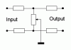
I am in the process of constructing a small, basic amplyfiying stereo mixer (see diagram below, which was taken from an earlier thread: https://www.electro-tech-online.com...-for-our-industrial-electronics-subject.6594/), however, i have (as an afterthought), decided to include a 'balance' control. I wondered what the best way to do this would be? The smaller diagram below shows my idea. A dual pot, with one of the pots connected in reverse to the other, so that when you turn it, one volume increases, and the other decreases (one of the two pots would be connected to the left channel, and the other to the right channel). Would this work? where I have written 'from Op-Amp', would infact be the output from the pot that controls the volume of that channel. Bearing in mind that I would then have two pots on each channel, would i need another amplifying circuit to bring the volume back up to an acceptable level? If i did need another amplyfying circuit after the mixing circuit, what would be the easiest way to do this? (I will probably use NE5532N op-amps all round) I know it would be easier to have to separate pots, one for each channel, so that you could manualy increase the volume on each channel as you wished, but i would rather have separate volume and balance controls. All suggestions welcome Thanks Tim
I am in the process of constructing a small, basic amplyfiying stereo mixer (see diagram below, which was taken from an earlier thread: https://www.electro-tech-online.com...-for-our-industrial-electronics-subject.6594/), however, i have (as an afterthought), decided to include a 'balance' control. I wondered what the best way to do this would be? The smaller diagram below shows my idea. A dual pot, with one of the pots connected in reverse to the other, so that when you turn it, one volume increases, and the other decreases (one of the two pots would be connected to the left channel, and the other to the right channel). Would this work? where I have written 'from Op-Amp', would infact be the output from the pot that controls the volume of that channel. Bearing in mind that I would then have two pots on each channel, would i need another amplifying circuit to bring the volume back up to an acceptable level? If i did need another amplyfying circuit after the mixing circuit, what would be the easiest way to do this? (I will probably use NE5532N op-amps all round) I know it would be easier to have to separate pots, one for each channel, so that you could manualy increase the volume on each channel as you wished, but i would rather have separate volume and balance controls. All suggestions welcome Thanks Tim
Attachments
Last edited by a moderator: