Hi,
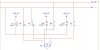
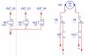
In attachment you can see a schematic to drive a dc motor with pwm clockwise and counter clockwise. The labels OUT are coming from a PLC output transistor and are driving an electromecanic relay (K5) and solid state relays (K6 and K7).
Direction 1 -> OUT2=0, OUT4=0 and OUT3=1
Direction 2 -> OUT3=0, OUT2=1, OUT4=1 (after 500ms from OUT2 turns on, since electromecanic relay are slower than solid state relays).
My PLC program takes care regarding the outputs and prevents that short circuit happens…
My doubts:
Should I put flywheel diodes?
If yes, where?
What happened (twice) is that K7 relay “borned” when I sttoped coming from Direction 1 - > I’m afraid this is related with back emf.
Thanks for your support.