Continue to Site

Welcome to our site!

Electro Tech is an online community (with over 170,000 members) who enjoy talking about and building electronic circuits, projects and gadgets. To participate you need to register. Registration is free. Click here to register now.

  • Welcome to our site! Electro Tech is an online community (with over 170,000 members) who enjoy talking about and building electronic circuits, projects and gadgets. To participate you need to register. Registration is free. Click here to register now.

B562 Vs B772 Transistors

Status
Not open for further replies.

Suraj143

Active Member
I'm doing an anode row design LED matrix (16X32).Doing a 1/16th scanning rate.I use B562 transistors to drive those 16 anode rows but the LEDs are very dim. B562 drives from a 25mA PIC pin via a 470R resistor.

I want to know will there be more bright on LED's if I use B772 transistors instead of B562?
 

Attachments

  • 2SB562.pdf
    264.7 KB · Views: 163
  • B772.pdf
    105.6 KB · Views: 158
  • Row.JPG
    Row.JPG
    62.3 KB · Views: 245
Both transistors have a minimum gain of around 80. Changing those is unlikely to make any significant difference.

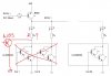
The base drive current is more likely 8 - 9mA, which gives over half an amp switching capability.
(the actual base current is set by the voltage across the 470R base resistor; 5V less the 0.6V or so base-emitter voltage of the transistor and less the slight positive voltage on the PIC output when sinking that current).

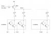
The LED current should be (5V - (ULN2803 voltage drop + LED voltage drop + anode driver drop)) / 47R
The voltage drops will be anything from around 2.5V to 4V or so, depending on the LED colour etc., so current (2.5 / 47) = 53mA down to (1 / 47) = 21mA

With 1/16th duty cycle, the equivalent average currents are 3.3mA down to about 1.3mA, which is likely why the LEDs are dim.

For 1:16 multiplex you can use LED current MUCH higher than the continuous current rating of the LEDs, as long as it's below the short term maximum.
The LED data sheet should give the required info, or post the LED type number so someone can work it out.

A resistor change is probably all you need, you have everything else working OK by the sound of things.

(Though thinking about it, you may need to keep any eye on the driver devices to ensure they are not getting too hot, with higher current through multiple LEDs).
 
32 rows of LEDs at 21mA each = 672mA. Your transistor is used as a saturated switch, not a linear amplifier so the base current for the little transistor must be 1/10th the collector current at 67.2mA for the LEDs to be bright when they are continuously turned on. Current gain is used for a linear amplifier that has a lot of collector to emitter voltage, not for a saturated switch.
Since you are multiplexing the LEDs at 1:16 duty cycle then the total LED current must be 672mA x 16= 10.8A and the transistor base current must be 1.1A or more. Your base current is only 8mA.
 
Wonderful information.every information is true.for the time being the only modification I could do is to change the 47R to a low value.because I have done the pcb for this, so in the driving stage I can only change transistor and the base resiator.

In my next pcb design I must think more on the row driving stage.

Thank you very much for the detail informations.
 
Is it ok if I lower the resistor to 15 ohms.
The base resistor? Then the extra high current will smoke your PIC. Replace the weak little transistor with a logic level P-channel Mosfet and reduce the value of the 47 ohms LED resistors a lot until the LEDs burn out.
 
Using mosfets and reducing the 47 ohm resistors to 15 ohms will make the LEDs brighter but still fairly dim.

Calculate the average LED current with the 15 ohms resistors:
If the LEDs are 2V red, and you use Mosfets then the peak current is 127mA and the 1:16 multiplexing reduces the average LED current to 127/16= 8mA. Will your LEDs survive 127mA peak currents? Will that be bright enough?
 
I can get **broken link removed** for less than US$5 from ebay. They use 4 MAX7219 chips and are excellent. Much easier than knitting your own.

Mike.
Edit, put two together and you have your 32x16 display.
 
I can get **broken link removed** for less than US$5 from ebay. They use 4 MAX7219 chips and are excellent. Much easier than knitting your own.

Mike.
Edit, put two together and you have your 32x16 display.

Hi Mike, I'm making a circle type LED matrix.So I want to make my own matrix using generic LED's.

Thanks.
 
Using mosfets and reducing the 47 ohm resistors to 15 ohms will make the LEDs brighter but still fairly dim.

Calculate the average LED current with the 15 ohms resistors:
If the LEDs are 2V red, and you use Mosfets then the peak current is 127mA and the 1:16 multiplexing reduces the average LED current to 127/16= 8mA. Will your LEDs survive 127mA peak currents? Will that be bright enough?

Hi Audioguru & Rjenc

I want to repair my already designed PCB without throwing as garbage.I made 5 PCBs. For future stuff I can make bigger changes.

my base current is (5-0.6)/470 = 9.3mA

Why I cant decrease the value of base resister down to 180R so the base current will be (5-06.)/180 = 24mA. Surely the PIC can supply until 25mA. Does the B772 can supply more current from 25mA than the B562?

Thanks
 
With a load of 24mA then the output voltage of the PIC will not be 5V, it might be 3.5V then the 180 ohm base resistor will provide a transistor base current of 15.5mA and the output of the transistor will be a minimum of 155mA. If all 32 rows are lighted then each row gets only 4.8mA and the 1:16 multiplexing reduces the average current in each row to only 0.3mA.

The datasheets for the 2SB772, 2SB562 and most other transistors show that they saturate pretty well when their base current is 1/10th their collector current but some are more sensitive than others so the little one might provide more current than the big one.
 
Now I'm got confused.

How can the PIC pin will be 3.5V when it passes 24 mA current? The datasheet says it can supply maximum of 25mA without any problem.
 
Now I'm got confused.

How can the PIC pin will be 3.5V when it passes 24 mA current? The datasheet says it can supply maximum of 25mA without any problem.

It doesn't say it can provide 25mA at 5V - you might try measuring it? - however, perhaps AG's suggestion was little overly cautious?, but he did say 'might'.

However, making minor changes will only provide minor differences, and you need a major redesign to make it work correctly - and a better understanding of multiplexing.

You might try 180 ohms and see if it helps a little.
 
I didn't read the datasheet of the PIC but I think its maximum allowed shorted to ground current is 25mA. Like any Cmos circuit its outputs have some resistance so if you try loading an output then its output high voltage drops.
 
If you use the max7219 chips they can illuminate 64 LEDs which would occupy 1/8 of a circle. Properly designed PCBs could be linked together into a circle to give you your 512 LED display. They are really excellent chips and form a really good display. Might be worth considering.

Mike.
 
Hi Audio & Others

Its time to change the design.Target is to get more bright from LEDs when they multiplexed @ 1/16th duty cycle.
Planning to replace the ULN2803 with A1015 transistors.I have to send logic 0 to the base of the transistors, that will be fine.

Any comments..!!
 

Attachments

  • Row (1).JPG
    Row (1).JPG
    95.1 KB · Views: 159
The 2SA1015 is a weak little PNP transistor with a maximum allowed current of only 150mA. It works poorly above 100mA. You are using it as an emitter-follower so it has a voltage loss of about 1.0V at 100mA. The output low from the PIC also has about 0.5V of voltage loss. Then the LED and its resistor will get only about 3.2V but won't many LEDs in a column be turned on which will destroy the 2SA1015 transistors?
 
The 2SA1015 is a weak little PNP transistor with a maximum allowed current of only 150mA. It works poorly above 100mA. You are using it as an emitter-follower so it has a voltage loss of about 1.0V at 100mA. The output low from the PIC also has about 0.5V of voltage loss. Then the LED and its resistor will get only about 3.2V but won't many LEDs in a column be turned on which will destroy the 2SA1015 transistors?

Is there any cheaper transistor solution out there?Does a PNP drop more than a NPN?
 
The voltage drop of a PNP and an NPN are almost the same. But instead of being a low voltage drop common-emitter switch, your PNP is a high voltage drop common-collector emitter follower, which also adds the voltage drop of the PIC output..
 
Status
Not open for further replies.

Latest threads

New Articles From Microcontroller Tips

Back
Top