Continue to Site

Welcome to our site!

Electro Tech is an online community (with over 170,000 members) who enjoy talking about and building electronic circuits, projects and gadgets. To participate you need to register. Registration is free. Click here to register now.

  • Welcome to our site! Electro Tech is an online community (with over 170,000 members) who enjoy talking about and building electronic circuits, projects and gadgets. To participate you need to register. Registration is free. Click here to register now.

Avr programmer component question

Status
Not open for further replies.

cobra148

Member
Hi,
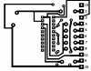
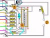
could some one please look at the attached schematic, and tell where to
connect the clk to the ic.

I am a complete beginner to electronics , and would appreciate some one
pointing me to the correct way to do this.

I have exposure box etching equiptment ect and have made a few pcb's in
the past, but I am not sure about where to connect the clk thats on the schematic.

Please forgive my lack of knowledge, glad to find this site though.

Thanks
 

Attachments

  • 1.jpg
    1.jpg
    203.9 KB · Views: 729
Here is what I have done so far

started the pcb and layout
 

Attachments

  • 1 PCB.jpg
    1 PCB.jpg
    92.9 KB · Views: 553
  • 1 PCB OVERLAY.jpg
    1 PCB OVERLAY.jpg
    136.3 KB · Views: 601
I'm confused about why you're asking this question. The 1.jpg image clearly shows it being connected to the CLK line of the AVR, look at the PDF of the AVR in question, one of them will be labeld CLK.
If you're a novice I would HIGHLY suggest you skip this particular endeavour and buy a programmer, such as the Dragon Digi-Key - ATAVRDRAGON-ND (Atmel - ATAVRDRAGON)
They're 49 dollars (US) and more than worth it. You'll have a development programmer that supports all basic and advanced programming and debugging features of all current and most future AVR products. You'll spend more than 49 dollars in time, effort, and material cobbling together a programmer that will have limited functionality.
 
Last edited:
No it doesnt

Hi,
Excuse my ignorance, but I attatched 1.jpg showing the schematic and a
capture of the AT90S1200 pinouts from the (data sheet pdf) along side of the schematic.

The capture from the pdf does not label ,show or mention CLK , just reset ,vcc, mosi miso, ect as you can clearly see.

And as my pcb drawing shows, I am fine with these connections, but not CLK.

Perhaps my question should have been, (NOT WHERE DO I CONNECT ON THE IC)
but rather ,as the pdf does not show CLK then what pin on the ic is known to be CLK ,as used by the experienced people out there.

Regards.
Please see the attached png picture. it is on page 34 of the ATMEL90s1200 datasheet. it is self explanatory and hope serves you.
 
Last edited:
Actually it seems to be figure 34 is on page 44 it's not page 34. I jumped the gun a bit there apparently the only place clk appears in the PDF is relating to the analog comparator input leakage current, I'm sure it's not related. If it's a custom pin there will be an .equ statement in the source code for the programmer, it will look like .equ ??? CLK. If you can post the code for the programmer we might be able to help, otherwise look at the code yourself to find the .equ statement. I don't see how figure 34 is obvious though the only thing that makes sense is that CLK is connected to the XTAL1, perhaps to reprogram the ATS90. You may already know this but the image shows you using status pins connected to the AVR, this will mean that you have to be using a program to allow direct access to the parallel port for the software that runs the programmer to function, even then it's using power from unused data lines which may or may not work.
 
Last edited:
Somebody e-mailed me to say, pin 13 of the db-25 to the avr as per schematic
must go to (SCK AVR PIN 19) for CLK.

But the on the schematic, it shows that pin 2 on the DB-25 connects to SCK
AVR PIN 19.

This has confused me more, but in reality , I dont want to program the
AT90S1200 anyway.

I want to build this programmer to program a AT90S2313.

The pc program that I will use is , sp12 at http://www.attiny.com/sp12.htm
The programmer schematic and build with photo info is at http://www.attiny.com/programmer.htm

The avr is to be programmed for this project at Avr Projects By Dim - Countdown timer for PCB development boxes

The hex was compiled by bascom-avr for the AT90S2313 and is attached here.
I want to use the AT90S2313 with external xtal instead of the tiny2313,
because its supposed to be more accurate.

I know the tiny2313 has internal osc but would prefer the external approach
for this project.

Please my friend, help me make some sense out of all this ,(new to avr's)so that I can get the programmer & timer built.

Thanks in advance.
 

Attachments

  • Bascom.zip
    20.1 KB · Views: 320
Status
Not open for further replies.

Latest threads

New Articles From Microcontroller Tips

Back
Top