Continue to Site

Welcome to our site!

Electro Tech is an online community (with over 170,000 members) who enjoy talking about and building electronic circuits, projects and gadgets. To participate you need to register. Registration is free. Click here to register now.

  • Welcome to our site! Electro Tech is an online community (with over 170,000 members) who enjoy talking about and building electronic circuits, projects and gadgets. To participate you need to register. Registration is free. Click here to register now.

AVR DDS ~ RS232 problem...

Status
Not open for further replies.

krazatchu

Member
Hi all~~


This is my first forray into programming microcontrollers...


I have been trying to build a pc controlled ddr... Ithink i'm having some problems with the rs232 interface...

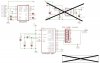
Originally I searched and found Jesper's MiniDDS at **broken link removed**

It uses the obsolete AT90S2313... I figured I might be able to get this working with an AT-Tiny 2313...

Then I found this very helpful page afer not being able to compile the original source ASM file (without errors)...

http://www.geocities.com/leon_heller/minidds.html

Leon Heller has rebuilt the code for Atmel AVR Studio... Thanks so much to him...

So far the code compiles great... and I can write it to the AT-Tiny2313 ... I changed the .include "2313def.inc" to .include "tn2313def.inc" .. .but either way it doesn't seem to make any difference...

I burnt the fuses on the Tiny2313 for external xtal 8mhz-up .. then I couldn't access the chip ...

So I said "Ah ha!" and added the 11.092 MHz xtal... then I could erase or verfiy no problem...

When I apply the power and run the chip in the circuit... I get a tone out... about 1kHz I think... when I unplug the xtal.. it stops.. and when I change the xtal, the tone changes... (It didnt do this b4 I burnt the fuses)....

So.. all that seems ok...

Now... other than swapping the at90s2313 for the at-tiny2313 ....
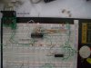
I also swapped the the max202 for a max232... since I found a kit rs232 interface... board, chip, connectors, was 4$....
For power I'm using a PC PSU...
I'm not using the AD557.. just the resistor ladder...

So... When I power up and plug in the rs232 cable... and then run the software from Jesper's site...
Then I try to set a freq... I jsut get 0000 in the output box... which is better than if I run the program without the rs232 cable.. then I get nothing in the freq output box...

I have read that there are some differences in the way the at tiny and the at90S communicate with the rs232 port... but I can't find anything more specific...

Could someone shed some light on it??

Thanks,
Michael
 
And here is the circuit diagram ....
 

Attachments

  • updated diagram.jpg
    updated diagram.jpg
    97.5 KB · Views: 1,481
From what I can understand of the code, it seem to be doing the right things to be a DDS. It should let you generate the frequencies you want with the resolution you want.

I don't know much about Atmel microcontrollers, and I am really confused by what lpm does in LOOP1, so I can't help with specifics.

The code says is was written for AVR-GCC in assembler mode, then converted for the Atmel AVR assembler, and you have put it on the AT-Tiny2313. There is nothing wrong with doing that, but if you do not understand the code that you are running, you cannot fault find it.

You have to be able to break it down and check each bit works, then you can find which bit doesn't.
 
I haven't done assembly code since 1997... I'm a complete beginer at microcontrollers....

From what I can find, LPM is "Load Program Memory" from AVR Studio's help file ... "Loads one byte pointed to by the Z register into the destination register Rd"

I think it loads the wave data from the lookup table ...
hmm, I wonder if there is an argument missing there...
 
krazatchu said:
When I apply the power and run the chip in the circuit... I get a tone out... about 1kHz I think... when I unplug the xtal.. it stops.. and when I change the xtal, the tone changes... (It didnt do this b4 I burnt the fuses)....

This is good and you are very close to full success. Your Tiny2313 operates correctly if you got a 1KHz output. As this 1KHz tone also depends on the correct setting of the crystal, I'm pretty sure that the RS232 part of the AVR code works correctly too.

Make sure you have set the communication parameter on the PC serial port to 115,200bps, 8,N,1. Check that the RX/TX connections are correct on the PC end because there are both straight and crossed serial connection cables. Download the datasheet of MAX232 and check that the AVR's RX/TX is actually connected to the TTL side of its buffers.

I have built exactly the same DDS circuit before using Tiny2313 and the PC host control software from Jesper worked as expected. But it was on a Win98SE system and I don't know if that would make a difference. I can't provide more details as I'm away from home.
 
I didn't actually check the tone, it just sounded like 1kHz to me... I will check it tomorrow with my pc... using a mic and some audio s/w I have...

I did set the the serial port to 115,200 (9600, 8N1 was default) ...

Hmm.. I will have to check that cable, didn't know there were crossed serial cables...

I did check the datasheet on the max232 its identical in pinout to the max202, I double checked the conections there....

I wonder If I set the baud rate really low and put an LED on the serial Tx output of the max232.... perhaps I could see it blinking when I send...

I might even boot up one of the spare win98 boxes in my office... I think we have 3 or 4 P3-800's laying around...

Thanks for the tips,
Michael
 
To check if the MAX232 is working correctly, on its pin 2, there will be a voltage of about +9V, and about -9V on pin 6, both measured with respect to 0V. Have you also connect the common ground(0V) to the serial port?

Can you also confirm that the following Tiny2313 AVR connections:

AVR pin3(TXD) to MAX232 IC pin 10 or 11
AVR pin2(RXD) to MAX232 IC pin 9 or 12

PC COM port TX to MAX232 IC pin 8 or 13, via cable
PC COM port RX to MAX232 IC pin 7 or 14, via cable

Added: There is an option/setting menu with the Jesper software where you can access via clicking on the top left hand corner. It took me sometimes to find out previously.
 
Last edited:
Allrighty.. just checked the pins and voltage...

5V supply = 5.30

Max232 Pin2 = 9.68
Max232 Pin6 = -8.64

Gnd check = ok

AVR Pin2 = Max232 Pin12
AVR Pin3 = Max232 Pin11

Cable TX = Max232 Pin13
Cable RX = Max232 Pin14

Cable GND = Max232 Pin15

Everything looks allright there...

Added: There is an option/setting menu with the Jesper software where you can access via clicking on the top left hand corner. It took me sometimes to find out previously.

Hey, what's this ??
There is a setting for DDS resolution... 24 or 32 bit...
The com port setting... Com1 is right...
And...
Synth Frequency is set to 2.4e+007 Hz ... hmm whats that for??
 
Hmm... I thought I toasted the max232.... was the avr instead

I decide to try my main pc instead of my cnc mill controller pc....
My main pc didn't have a rs232 port on the back, but has one on the main board... so I dug thru the old pc pile... and found a connector (didn't bother to check the pin out) ...

I plugged it in and got some strange frequency reading from the program window... then I tried my mill pc again... got another strange reading... (3,116,821.4545Hz & -3,072,000,000.0000Hz) ...

So then I swapped the AVR and its back to 0000Hz (on mill pc) like it was before...

I will have to find the right connector for the mainboard b4 I try that agian...
I think it's at home.... I'll find it tonight..

I think I dig a bit more thru the pc pile and find a working p3 with win98...

I'll let u know how that goes....
 
hmmmm...

When I connected it to a P3 800... I get the strange numbers agian...

Perhaps I did let the magic smoke out of Max232....

I think I will pick up a max202 tomorrow and maybe a few parts for another DDS in case the max202 doesnt make a difference...

I think I will try this one instead....
http://www.scienceprog.com/avr-dds-signal-generator-v10/

Or if anyone has any other suggestions...

Michael
 
krazatchu said:
And...
Synth Frequency is set to 2.4e+007 Hz ... hmm whats that for??

I'm 99% sure it is for you to enter the frequency of the crystal that you are currently using, in this case, 11059200Hz.

Added: you first post indicated using a 11.092MHz crystal, is it a typo and you are actually using a 11.059MHz crystal?
 
Last edited:
You might move C7 (5V to GND bypass) closer to the MCU, and add another on the other 5V/GND rails, and another for the LS04 5V/GND rails. Some parts are picky about this.
 
EBCL, that's what I think also...

MNEARY, thanks for that tip... I'll try it out later as
I've already built the DDS project from http://www.scienceprog.com/avr-dds-signal-generator-v10/ ...

It doesnt quite give me the accuracy that I want... but it only took a day to build including one trip across town to the electronics market, bread boarding it and then transfering to a pcb...

I'll prolly get around to building Jesper's original DDS by Saturday...

Here is a pic of the DDS I build... inside the box isn't to pretty but it works...

Thanks,
Michael
 

Attachments

  • dds.jpg
    dds.jpg
    85.8 KB · Views: 650
Status
Not open for further replies.

Latest threads

New Articles From Microcontroller Tips

Back
Top