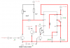
Using this basic 555 timer circuit in my car to give a 10 second or so pulse.......
**broken link removed**
It's triggered by a short positive pulse but has to output a much longer negative pulse,which I can do.
What I also need which I can't figure out is to disable it when the car's ignition is turned on.I can quite easily open circuit the supply to the timer with a relay,but I really want to keep it all solid state if possible.
So is there anywhere in the above circuit I can apply + 12 volts to that will inhibit it from working?
Chris.
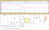