Continue to Site

Welcome to our site!

Electro Tech is an online community (with over 170,000 members) who enjoy talking about and building electronic circuits, projects and gadgets. To participate you need to register. Registration is free. Click here to register now.

  • Welcome to our site! Electro Tech is an online community (with over 170,000 members) who enjoy talking about and building electronic circuits, projects and gadgets. To participate you need to register. Registration is free. Click here to register now.

Automotive RPM converter for tachometer

Status
Not open for further replies.

Sketch_hs

New Member
I'm doing an engine conversion on a 1988 Mazda Rx7

I'm putting in a I6 engine where the oringinal motor is a rotary engine that has a tach signal like a 4 cylinder.

So how can I make the stock tach work properly with the new 6 cylinder output?

Any ideas on circuits or maybe you guys know of products already made that do this?
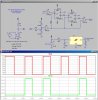
 
I designed a board that does this for a 4 cyl to 6 cyl swap. It was pretty easy and was microcontroller based. All you really need to do is measure the incoming frequency then bump it up 50% and spit it back out to an N-FET with a resistor pullup to 12v. At least thats what I did.
 
A bit like mine then

**broken link removed**

Although mine has a wide range of variable ratios and has been designed to be fairly bombproof. Its undergoing a redesign at the moment as the one in the picture was an early prototype but so many people wanted them that I never got round to making a "neat" version.
 
I designed a board that does this for a 4 cyl to 6 cyl swap. It was pretty easy and was microcontroller based. All you really need to do is measure the incoming frequency then bump it up 50% and spit it back out to an N-FET with a resistor pullup to 12v. At least thats what I did.
Do you mean 6 cyl to 4 cyl swap? I would expect a 6 cyl engine to have a higher pulse frequency output (from the distributor I assume) than a 4 cyl, so I would think you want to reduce the signal frequency, not increase it.
 
If you want to build you own you could use a pulse swallower circuit generated by a divide by 3 flip-flop circuit and an AND gate as shown in the attached (CD CMOS ICs shown). The divide by 3 circuit is used to inhibit (swallow) every third pulse through the AND gate giving you the 2/3 (4/6) division you need.

Of course you will need to filter the power, and provide proper buffer circuits at the chip input and output to match the input signal and provide the desired output signal.
Divide by 2-3.gif
 
Last edited:
Do you mean 6 cyl to 4 cyl swap? I would expect a 6 cyl engine to have a higher pulse frequency output (from the distributor I assume) than a 4 cyl, so I would think you want to reduce the signal frequency, not increase it.

Yeah, you're right. I bumped up the period, not the frequency :) Little bit of difference between the two.

This was the (bery blurry) board I made...
**broken link removed**
 
Last edited:

Attachments

  • TwoThirds.jpg
    TwoThirds.jpg
    221 KB · Views: 2,565
I have the same problem. 4cyl to a 6cyl swap (vw).

could i get someone to send me a parts list and diagram? i would like to try my hand at micro-controllers. If i need software, please also, i would take suggestions. neat tinkering huh..
instructions would be great also.
JJJeffcoat@comcast.net

I designed a board that does this for a 4 cyl to 6 cyl swap. It was pretty easy and was microcontroller based. All you really need to do is measure the incoming frequency then bump it up 50% and spit it back out to an N-FET with a resistor pullup to 12v. At least thats what I did.
 
Status
Not open for further replies.

Latest threads

New Articles From Microcontroller Tips

Back
Top