Continue to Site

Welcome to our site!

Electro Tech is an online community (with over 170,000 members) who enjoy talking about and building electronic circuits, projects and gadgets. To participate you need to register. Registration is free. Click here to register now.

  • Welcome to our site! Electro Tech is an online community (with over 170,000 members) who enjoy talking about and building electronic circuits, projects and gadgets. To participate you need to register. Registration is free. Click here to register now.

Audio feedback problem

Status
Not open for further replies.
You have 4.7k for R34 when it is supposed to be 4.7 ohms.

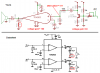
Your circuit has a few audio attenuators:
1) R135 into the very low input impedance of R137, R138 and Q39 reduce the detected signal by about 1/23.
2) R100 and R38 attenuate the audio signal by 1/11.
3) R147 and the input of Q42 attenuate the audio by about 1/11.
So the total attenuation is almost 1/3000 times.

Your circuit has audio gain coming out of its ears. No wonder it oscillates:
1) Q39 has a voltage gain of about 150 if C43 is connected to ground.
2) Q42 has a voltage gain of about 100.
3) The 741 opamp has a voltage gain of 22.
4) Q19 has a voltage gain of 83.
5) The TDA2822 has a voltage gain of 100.
The total audio gain is 2,740,000,000 which is rediculous.
Your volume control is not a voltage divider.

The feedback from the power supply is injected into the audio by all the bias resistors for the transistors and by R151.

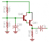
I was wondering what is Q40 and Q41??? They make a darlington (drawn oddly) but it is not needed.
 

Attachments

  • radio's amplifier.PNG
    radio's amplifier.PNG
    42.6 KB · Views: 179
  • darlington.PNG
    darlington.PNG
    4.8 KB · Views: 175
AG, how did you calculate transistor amplifier gains? I looked through the thread and couldn't find any mention of the value of Vcc. As we know, gain for these amps is highly dependent on Vcc.
Also, you left out the attenuators caused by R57 and R58 (which I mentioned above).:) I came up with about 100dB attenuation, which is 100,000.
 
I can't believe how much gain you are throwing away. Here is a list of the resistors that are at the beginning of each attenuator, along with the approximate attenuation of each divider:

R135 -9dB
R147 -24dB
R57 -33dB
R58 -12dB
R100 -22dB

You are throwing away approximately 100dB of gain! Throwing away gain means more noise and more distortion at the output.

I follow you there. It's just that with such a broad range of incoming signal strengths I had to evenly distribute the gain over a series of amplifiers to prevent clipping even with AGC.
The AGC could be better. I would need to control two or three amplifiers in order for it to cover the entire range but I am concerned with power since I plan to run it portable as well as base station. So I sacrifices with a manual 2nd IF gain control for the really strong signals.
 
AG, how did you calculate transistor amplifier gains? I looked through the thread and couldn't find any mention of the value of Vcc. As we know, gain for these amps is highly dependent on Vcc.
Also, you left out the attenuators caused by R57 and R58 (which I mentioned above).:) I came up with about 100dB attenuation, which is 100,000.
I think he said the power supply is 9V.
Most of his transistors are loaded down by their load so they do not have a gain as high as 200.
I was slow replying because I was eating brunch at the same time so i didn't see his revised schematic with R57 added.
 
I think he said the power supply is 9V.
Most of his transistors are loaded down by their load so they do not have a gain as high as 200.
I was slow replying because I was eating brunch at the same time so i didn't see his revised schematic with R57 added.

No, I'm using 5.6 volts. Don't ask me why I'm using that. It's just and old power supply I put together years ago and it has an output closest to 6 volts. I have a small sealed lead acid battery that is 6 volts. I have charged it from the sun many times. I think it will make a nice portable rig.

And guru? Have you ever designed AGC before? Now who doesn't know that AGC is DC? Come on now. You think I don't know that? Give me at least a little credit will ya? You know you are such an intelligent guy, but you can be rude at times. (Oh man, the things we have to put up with in this world......bbbrrrrooootttthhhheeeerrrr). Now. You ever hear of of rectification? How about ripple filtering? Maybe that is the reason "attack time" is considered in an AGC loop.

Alright, I'm gonna lay off of you. You have helped me many times and you are good about helping people. I'll put credit where credit is due. Now my AGC uses the audio. Then it RECTIFIES it and uses it to control the bias of an IF stage.

No hard feelings man. I still like you :) .... I just feel sorry for some of the newbies around here. ;)
 
Last edited:
Now my AGC uses the audio. Then it RECTIFIES it and uses it to control the bias of an IF stage.
Then you have an audio compressor, not AGC. The gain of your IF changes with the amount of modulation, not with the strength of the signal.

AGC rectifies the IF's radio signal (not audio) and uses the resulting DC to reduce the gain of the IF amp then reduce the gain of the RF amp.

The AM detector diode rectifies the IF's radio signal and makes audio for the amplifier and makes a DC voltage proportional to the signal strength that is used for AGC.
 
No, I'm using 5.6 volts. Don't ask me why I'm using that. It's just and old power supply I put together years ago and it has an output closest to 6 volts. I have a small sealed lead acid battery that is 6 volts. I have charged it from the sun many times. I think it will make a nice portable rig.
I saw somewhere in this thread that you were using 5.6V, but I thought it must be just for the output amp, because the base of Q19 would only be biased at 0.47V - not high enough to provide significant collector current.
 
I saw somewhere in this thread that you were using 5.6V, but I thought it must be just for the output amp, because the base of Q19 would only be biased at 0.47V - not high enough to provide significant collector current.
Shhhh. Q19 is an old AC127 germanium transistor.
 
Shhhh. Q19 is an old AC127 germanium transistor.

Where do you see that it is germanium? I don't even see that on the data sheet. Anyway I wanted a low frequency transistor and the only other medium power transistors I had was some 2N2222's. I know those are high frequency and I don't want that. Wouldn't be much to re-bias one stage if I need to change it.

As far as a compressor. Yeah I will agree but that's all AGC is anyway. It is not uncommon to use the audio as the source. I am trying to keep it low power or minimum circuits so I figured I would get more drive from the audio. It works very well because loud audio peaks will cause it to clip and with a fast attack time I can minimize the clipping. It most certainly will follow the signal strength so all and all it is a two for one AGC and compressor. In keeping with minimum circuitry I still have a 1st IF gain control & 2nd IF gain control. It's intent is to be a quality communications receiver that can be run portable.

About the only problem I have left which is very minor is when I hook it to an old linear power supply I will get a small amount of "common mode hum". Inside the radio I did all I can do like shielding the 1st LO and choking the incoming power and reducing the size of audio couple caps to minimize lower audio frequency coupling. Not too much though. If you have looked inside a good linear power supply that is clean, you will notice a capacitor atleast the size of a dog food can. I want to stay linear do to the serge impeadance of a linear power supply. I do not believe I would even attempt to use a switcher with SSB or CW. Well I found this article which suggest ways to get around it with smaller caps. I found it rather interesting:
Direct%20Conversion%20Receivers.pdf

Pay no attention to the title but they discussed some techniques to deal with it. Hear is part of it....

"A final problem of significance in DC receivers is hum. This hum is most prevalworse
as the operating frequency is increased.
use ac-operated do power supplies. It is worsened
antenna is attached to the receiver. An inferior
chassis) complicates the hum problem
"common-mode hum." This very annoying
power and a coaxial-fed antenna. The
antenna getting into the ac power-
1 20-Hz hum. This energy is radiated
causing it to enter the receiver
same frequency. This note describes
becomes
we
end-fed
to the receiver
for this fault is
using battery
receiver radiation via
syndrome
fault is
supply
by the
front end along with the desired signal on the
cures for this and the other problems listed above.
by
the
rectifier diodes and being modulated by
power-supply leads and ac line cord,
Something needs to be said also about unwanted AM-signal detection of commercial
2
"
 
Was I correct in guessing and joking that your Q19 transistor is an old germanium AC127??

A 2N2222 or 2N3904 transistor is fine for audio. They have a frequency response up to about 300MHz. A capacitor from collector to base reduces the frequency response if you want.
Your circuit has way too much audio gain. It also has a lot of audio attenuation.
The transistors are powered directly from the raw power supply voltage without any filtering which causes hum.
 
Where do you see that it is germanium? I don't even see that on the data sheet.

If it's an AC127, the 'A' signifies it's germanium (a 'B' would be silicon).

Anyway I wanted a low frequency transistor and the only other medium power transistors I had was some 2N2222's. I know those are high frequency and I don't want that. Wouldn't be much to re-bias one stage if I need to change it.

Sorry, but a 2N2222 is exactly the type of transistor you should be using, it's essentially an audio or switching transistor, not an RF device.

As far as a compressor. Yeah I will agree but that's all AGC is anyway. It is not uncommon to use the audio as the source. I am trying to keep it low power or minimum circuits so I figured I would get more drive from the audio. It works very well because loud audio peaks will cause it to clip and with a fast attack time I can minimize the clipping. It most certainly will follow the signal strength so all and all it is a two for one AGC and compressor. In keeping with minimum circuitry I still have a 1st IF gain control & 2nd IF gain control. It's intent is to be a quality communications receiver that can be run portable.

You appear to have no idea what AGC is for?, audio compression will be really VERY useless on a radio, and make a badly performing design. Try looking at any commercial radio - they use IF and RF (delayed) AGC, and this is what you need to do.

About the only problem I have left which is very minor is when I hook it to an old linear power supply I will get a small amount of "common mode hum". Inside the radio I did all I can do like shielding the 1st LO and choking the incoming power and reducing the size of audio couple caps to minimize lower audio frequency coupling.

As Audioguru says, your design is completely lacking in anything to stop oscillation, feedback, and hum - stages need individual decoupling. You also really need to dump most of it, it's not needed, and is only making things worse instead of better.

The section you have posted is completely bizarre, if you hadn't mentioned it's supposed to be part of a radio I wouldn't have known.

I can only suggest you start entirely from scratch, and consult some existing circuits to see what you need, and what you don't - if you don't have an ARRL or RSGB Handbook, then go any buy one immediately.
 
....and, rather you work off the audio or off the IF's, it will still respond to modulation because in AM the signal strength is increased with modulation. It is double for 100% modulation if the voice peaks to 100%. This is particularly true with SSB where there is no carrier unless there is modulation, there will be no signal at all or speaking from the receiver end, there will be no IF, that is provided you have a clean design in which case you should have no IF at all unless there is an incoming signal.
 
Sorry, but a 2N2222 is exactly the type of transistor you should be using, it's essentially an audio or switching transistor, not an RF device.

You do not want to use transistor with high hfe in audio. They are prone to feedback and spurious responses.

The audio has only had a minimal amount if filtering added to it of which I will post when I get more time. It is working great and is completely linear with the gain distributed evenly among the stages. This is something that must be carefully adhered to in short-wave reception. So yes, it may appear a bit non-conventional but you cannot expect the audio for a short-wave receiver to appear anything like an FM network type of receiver lsuch as cell phones etc. Nothing at all like it.
 
You do not want to use transistor with high hfe in audio. They are prone to feedback and spurious responses.

Yes you do, in fact audio transistors are generally the highest hfe of all transistor types - I've no idea where you've imagined 'prone to feedback and spurious responses' from? - if it's your circuit shown, it's because it's 'designed' completely wrongly.

The audio has only had a minimal amount if filtering added to it of which I will post when I get more time. It is working great and is completely linear with the gain distributed evenly among the stages. This is something that must be carefully adhered to in short-wave reception. So yes, it may appear a bit non-conventional but you cannot expect the audio for a short-wave receiver to appear anything like an FM network type of receiver lsuch as cell phones etc. Nothing at all like it.

Have you ever seen a circuit for a shortwave radio?, obviously not - your audio stages are incredibly poorly designed, and won't work well at all - you could simply throw every transistor stage out of there, leaving the opamp and output IC and greatly improve performance. You hardly need the opamp either, and could repelace that by a correctly designed single transitor stage, but an opamp is far easier to design.
 
Does anybody use Single-Sideband-Suppressed-Carrier anymore????? Why?
 
Yes you do, in fact audio transistors are generally the highest hfe of all transistor types - I've no idea where you've imagined 'prone to feedback and spurious responses' from? - if it's your circuit shown, it's because it's 'designed' completely wrongly.


Have you ever seen a circuit for a shortwave radio?, obviously not - your audio stages are incredibly poorly designed, and won't work well at all - you could simply throw every transistor stage out of there, leaving the opamp and output IC and greatly improve performance. You hardly need the opamp either, and could repelace that by a correctly designed single transitor stage, but an opamp is far easier to design.

LOL....and.....Ha-ha-ha-ha..... You give me a good laugh this morning as I'm sitting here listening to hams talking in SSB with perfect quality audio. I just installed the BFO yesterday.

And where do you think I get my designs for the audio? They are slight variations of stuff from the ARRL....lol.

Trust me. Audio design for SSB is nothing like FM. That's what your talking about. Stuff that comes in perfectly clear at the same decibel rate continuously. No challenge at all.

Oh, high frequency (hfe)? Who told you that? Somebody told you wrong. You want high hfe in stuff like rf front ends like an LNA where you want maximum gain (S/N). Maybe in small signal amplifiers. As you go down in frequency and start adding power, you do not want high hfe. They tend to want to operate at there rated frequency and so , especially at audio, they tend to amplify the high frequencies which could be undesired hiss or the creation of higher frequency oscillations. Also in rf Power Amps high hfe can produce parasitic and spurious emissions unless that is the frequency you are designing for. Have you ever looked at a Motorola rf Data Book? Look at the hfe's and recommended frequencies of the transistor usage. You will usually find they are rated about three times the desired frequency. (I just looked up an MRF454 but didn't list "hfe").

Bottom line...It is not always desirable to have maximum gain or hfe which does the same thing. High gain for higher frequency transition. Consider the mixer circuit. Normally you will use a post mixer amp with an attenuator which helps limit the high signal levels and lowers the impedance or the crystal filter may pick up undesired noise.

Oh, did I mention I'm using a long wire antenna that is practically lying on top of my computer and I'm listening to guys talking half way across the country at 75 to 150 watts most of them. I must be doing something right ;)
 
LOL....and.....Ha-ha-ha-ha..... You give me a good laugh this morning as I'm sitting here listening to hams talking in SSB with perfect quality audio. I just installed the BFO yesterday.

And where do you think I get my designs for the audio? They are slight variations of stuff from the ARRL....lol.

They bear no resemblance to anything I've seen in the ARRL Handbook, of which I have a copy - if they are 'slight' variations, then they aren't so 'slight' and you've bodged a selection of circuits togther at random.

"perfect quality audio" from SSB? :p :p :p :p

Trust me. Audio design for SSB is nothing like FM. That's what your talking about. Stuff that comes in perfectly clear at the same decibel rate continuously. No challenge at all.

I've been a radio amateur since the really 70's (G8MMV), I know perfectly what SSB is - and it doesn't need (nothing does) an amplifier followed by an attenuator, followed by an amplifer, followed by an attenuator etc.

Not one of the transistor stages is needed, or doing anything.

Oh, high frequency (hfe)? Who told you that? Somebody told you wrong. You want high hfe in stuff like rf front ends like an LNA where you want maximum gain (S/N). Maybe in small signal amplifiers. As you go down in frequency and start adding power, you do not want high hfe. They tend to want to operate at there rated frequency and so , especially at audio, they tend to amplify the high frequencies which could be undesired hiss or the creation of higher frequency oscillations.

Sorry, you're talking complete rubbish, and completely the wrong way round - you don't even get high gains at high frequencies (like LNA's etc.).

For a simple example, check the spec on a BC109, a transsstor specifically designed for high quality audio use.

Also in rf Power Amps high hfe can produce parasitic and spurious emissions unless that is the frequency you are designing for. Have you ever looked at a Motorola rf Data Book? Look at the hfe's and recommended frequencies of the transistor usage. You will usually find they are rated about three times the desired frequency. (I just looked up an MRF454 but didn't list "hfe").

Bottom line...It is not always desirable to have maximum gain or hfe which does the same thing. High gain for higher frequency transition. Consider the mixer circuit. Normally you will use a post mixer amp with an attenuator which helps limit the high signal levels and lowers the impedance or the crystal filter may pick up undesired noise.

So you're amplifying and attenuating again - why bother? - why not just not amplify in the first place?

Oh, did I mention I'm using a long wire antenna that is practically lying on top of my computer and I'm listening to guys talking half way across the country at 75 to 150 watts most of them. I must be doing something right ;)

Considering you were complaining about low quality, feedback, and oscillation (as it's all designed wrong), somehow I'm not convinced :D
 
Status
Not open for further replies.

Latest threads

Back
Top