Continue to Site

Welcome to our site!

Electro Tech is an online community (with over 170,000 members) who enjoy talking about and building electronic circuits, projects and gadgets. To participate you need to register. Registration is free. Click here to register now.

  • Welcome to our site! Electro Tech is an online community (with over 170,000 members) who enjoy talking about and building electronic circuits, projects and gadgets. To participate you need to register. Registration is free. Click here to register now.

Audio amplifier: LM386

Status
Not open for further replies.
There are circuits in the datasheet that work fine. Can't get any simpler than those...

j.

Oh- important safety tip, too. They aren't kidding about bypass caps! Use 'em!
 
alright, thanx . . . i didn't even see the circuits in there :oops:

Got a couple questions . . .

1. Will the circuit that has a gain of 20 work for me? I really don't need it to be very loud.

2. Do I need a bypass cap for the one with 20 gain? What value should the bypass cap be?

Thx :lol:
 
This is the circuit I use. It works fine. The little caps are ceramic. The big ones are electrolytic.

I put a buffer in front of it, because I never want to "wonder" what the input impedence is. You may notice that the input buffer has a pull-up resistor on it. It's not really a pull up, but rather meant to form a voltage divider with the lower half of the divider with is on my text-to-speech board. Otherwise, just put a 33k in the lower half to bias the input to mid-rail.

j.
 

Attachments

  • lm386scheme.gif
    lm386scheme.gif
    12.9 KB · Views: 1,064
Here's the board layout. Needless to say, the back layer is a solid ground plane :wink:

j.
 

Attachments

  • lm386layout.gif
    lm386layout.gif
    10.5 KB · Views: 989
i dunno . . . thats a little big for me. If that simple circuit will work on the datasheet, thats what i wanna go with (sory for being so picky :lol: ). so if someone could answer those questions i put up earlier, it would be greatly appreciated. Also, I still don't grasp the concept of how a ground plane is connected . . . just to ground?

I'm almost ready to put this thing together :lol:
 
zachtheterrible said:
I thought that ground is the same as the negative side of a battery.

"Ground" is in its truest sense just that -- the ground, or as it is more commonly referred to across the pond, "earth". However, the term "ground" has come to be used for any common return current path, and in reality could mean different things in different applications -- and is not always the negative side of a DC circuit. Not all that long ago, for example, automobiles and trucks used a "positive ground" system whereby the positive side of the vehicle battery was connected to the chassis. (Mack trucks used this method into the 1970's.)

In an AC circuit, "ground" is most often held at the 0V level -- which puts it between the "positive" and "negative" extremes.

Here in the US, there is often a lot of confusion caused by the overlapping use of this term, and it should be remembered that "chassis" is not always "ground", and that "ground" is not always an earth ground.
 
Is This Small Enough?
The 56 Ohm Resistor is for power limiting when using Headphones.
Bypass it for use with speakers.
 

Attachments

  • lm386_111.jpg
    lm386_111.jpg
    52.6 KB · Views: 964
so if someone could answer those questions i put up earlier, it would be greatly appreciated

If giving you a schematic and two board layouts doesn't answer your questions, then I just don't know what you're asking. My circuit is essentially from the datasheet, except I've tested it and it works. If you don't need the buffer on the front end, don't include it.

Also, I still don't grasp the concept of how a ground plane is connected

You see all them triangles pointing down in my drawing? They all connect to ground, or common, or the return, or the negative rail, or whatever you want to call it. In this case, they all connect to the "ground" plane, which is the negative end of the battery or the 0V end of the supply, which may or may not be connected to earth ground (probably not). Yeah, we play loosey goosey with the term "ground" but I've never heard any one call it a negative plane or common plane.

j.

j.
 
Thanx john, thats wut i figured how ground plains are made but wasnt sure :lol: And if my amp that i want to make won't work, ill make yours minus the buffer :D

Thanx chrisp for the ground tutorial, im finally getting the whole ground, negative, positive . . .

Thanx chemelec for the picture.

I posted the amp that i want to make. Sorry for the awful drawing. I couldnt find an lm386 on switchercad :cry: . It has minimal parts, and i'm wondering if it would serve my purpose. It only has a gain of 20. I would imagine this would be enough to drive headphones . . . is it?


thanx so much, I'm alsmost there :lol:
 

Attachments

  • 20_gain_lm386.jpg
    20_gain_lm386.jpg
    20.4 KB · Views: 934
Gain has Almost Nothing to do with being able to drive Headphones.
And an LM386 will Easily drive a speaker, so Headphone are a cinch.

Whenever you drive Headphones from an Amplifier, You ALWAYS ADD a Series Resistor to Reduce Power. (Usually 50 to 150 Ohms) It Saves Distroying the Headphones and your Ear Drums.

Besides an LM386 has a Voltage Gain of 26 dB Min and 46 dB Maxium.
That a lot more than 20.

That Photo of mine is set at 46 dB.

Gary
 
Gain has Almost Nothing to do with being able to drive Headphones.

I wasn't too sure about that, but thanx 4 correcting me. :lol: I know what you're talking about now. Everything just clicked.

Well, i guess what this all comes down to is will this circuit work for my purposes? I am only going to be using headphones for this circuit. Also, if i want to increase the gain, will I have to do anything other than connecting pins 1 n 8 with a capacitor and resistor?
 
ALRIGHTY THAN!!! I'm good 2 go :lol:

1 mor thing . . . i can probly use a .0047 uf cap instead of that .005 uf right?

Actually 2 mor thing . . . can i use a .1 .01 or .001 cap for decoupling?(which one) i have a ton of these caps. And decoupling the pwr supply just means that its placed over the battery leads, right?
 
Hi Zach,
1) I'm glad that you are not using John's 0.1uF cap across the input, because when your 10K volume control is half-resistance, it will cut all frequencies above only 640Hz. Maybe that was to filter his buzzy speech synthesizer.
2) See if the TDA7000 is able to drive a 10K volume control. Harry's 100nF output cap will rolloff low frequencies below 160Hz when driving a 10K volume control. Maybe a 20K volume control is more suitable.
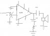
3) You must use a ceramic supply decoupling cap of 0.1uF. It should be mounted as close to the LM386's pins 6 and 4 as possible. The 0.047uF (not 0.0047uF) cap at the output should also be ceramic. You will also need a 100uF cap mounted anywhere and connected across the battery input to all circuits.
4) You don't need a ground plane for this simple audio amp. An ordinary PCB or even Veroboard will work fine.
5) You don't need a bypass cap at pin 7.
6) Don't use a resistor in series with the 10uF cap across pins 1 and 8. It will add extra gain only at low frequencies (bass boost) which you certainly don't need since your receiver has de-emphasis (like all FM receivers have), but your simple transmitter doesn't have a corresponding pre-emphasis (like all FM radio stations have) so it will sound very muffled and bass-boost will just make it worse.
7) Your headphones will need about 500mV RMS for loud peaks. Harry says that the TDA7000 produces 70mV, therefore you need a gain of at least 7.1. The gain of 20 without the cap across pins 1 and 8 will be fine (enough extra gain to turn-up the volume when the input audio is low).
8) Use a logarithmic, not linear, volume control.
 
Thanx soo much :lol:
The 0.047uF (not 0.0047uF) cap at the output should also be ceramic.
I realized that just after i turned off the computer :evil: . i felt like slapping myself, but i figured everyone helping me out with this is pretty bright :lol:
Use a logarithmic, not linear, volume control.
The only volume controls that ive seen are HUGE like as big as the circuit, is there anything smaller? And what is the difference between a logarithmic and a linear volume control?

thanx so mjuch :lol:
 
Hi Zach,
Most "ordinary" volume controls are 7/8" diameter. Many are 5/8" and I have some that are 1/2". Is that too big?

Your hearing and sight are logarithmic in order to have a wide range of intensity. You can hear sounds from about 40dB to about 120dB or more (louder than 120dB is painful). Each 20dB increase or decrease is 10 times of voltage change across a speaker, so from 40dB to 120dB is a voltage range of 10,000 times!
If you use a linear volume control then most of its range will be crammed into the low end. From maximum to halfway rotation of the knob will reduce the voltage only one-half, which doesn't sound much lower. Turn the knob from maximum to 1/3 rotation then it sounds about half as loud. Getting a voltage change of more than 20 times is difficult with a linear volume control.
A logarithmic volume control has its range spread evenly throughout its rotation. Its range of voltage change is at least 1000 times. It attenuates more and more when you turn it down, exactly what your hearing requires. From maximum to 3/4 rotation, the voltage is reduced to about 1/3rd (about half as loud). Down some more to 1/2 rotation and the voltage is reduced to about 1/10th (half again as loud). Etc.
 
that makes sense, thanx :lol:.

Got another question that does not relate to the lm386, actually to the tda7000. Connectig pins 7 n 9 is a .0033 uf cap. The only .0033 uf cap that i could find was a .0033MFD 100v mylar. is that kosher?

Ive been looking into getting a POT. Here's the POTS that you can get

https://www.allelectronics.com/cgi-...nd,INVENTORY.model&match=&searchtype=&start=0

The thing is, I can't find anything about logarithmic . . . everything is linear, what should I do?

And lastly but not leastly, would a 100 uf cap work for the output of the lm386? i cant seem to find a 250 uf. if that wont work, will a 220 uf work? thats the closest i can find

Again, I am so greatful for all the help, I would be lost without it :lol:
 
1) I'm glad that you are not using John's 0.1uF cap across the input, because when your 10K volume control is half-resistance, it will cut all frequencies above only 640Hz. Maybe that was to filter his buzzy speech synthesizer.

I never ran the math on it. I musta put it there for some reason (probably something to do with the speech synthesizer) but all I know is right now it's hooked up to an ICL8038 and it has good response from 200 Hz to 12 kHz (I don't know how the response is above that, because I can't hear it. I'll ask the dog.)

The proof's in the puddin'. So run your equations all day, it sounds good from my house :D (The smiley indicates I'm just foolin' around, so don't flame me)

j.
 
zachtheterrible said:
that makes sense, thanx :lol:.

Got another question that does not relate to the lm386, actually to the tda7000. Connectig pins 7 n 9 is a .0033 uf cap. The only .0033 uf cap that i could find was a .0033MFD 100v mylar. is that kosher?

That's fine!.

Ive been looking into getting a POT. Here's the POTS that you can get

https://www.allelectronics.com/cgi-...nd,INVENTORY.model&match=&searchtype=&start=0

The thing is, I can't find anything about logarithmic . . . everything is linear, what should I do?

If they don't stock log pots find a better company who does, is a standard component, nothing rare about it!. It will still work with a linear pot, just that the adjustment will be rather sudden.

And lastly but not leastly, would a 100 uf cap work for the output of the lm386? i cant seem to find a 250 uf. if that wont work, will a 220 uf work? thats the closest i can find

A 220uF is fine, 220 is a preferred value, 250 isn't!. Bear in mind the tolerances on components, electrolytics are often -50% +100%, so fairly obviously there are not often terribly critical.
 
Status
Not open for further replies.

Latest threads

New Articles From Microcontroller Tips

Back
Top