Continue to Site

Welcome to our site!

Electro Tech is an online community (with over 170,000 members) who enjoy talking about and building electronic circuits, projects and gadgets. To participate you need to register. Registration is free. Click here to register now.

  • Welcome to our site! Electro Tech is an online community (with over 170,000 members) who enjoy talking about and building electronic circuits, projects and gadgets. To participate you need to register. Registration is free. Click here to register now.

Audio advice please

Status
Not open for further replies.

billybob

Active Member
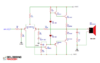
I need some help making sure this is a good circuit to go by.
I know it's probably not the greatest, but would is it efficient enough? Will it even work as intended.
This is a friend's project I am just helping him with it. He wants around 200 watt capability.

Thank you,
Ben
 

Attachments

  • 2SC5200-amplifier-circuit.png
    2SC5200-amplifier-circuit.png
    71.8 KB · Views: 273
The amplifier circuit from India has errors:
1) Its maximum output is only 45W into 4 ohms.
2) It is not biased correctly so it will produce awful crossover distortion all the time.
3) Its capacitor C2 has such a high value that it will kill most audio frequencies.
4) It has no detailed audio specs.

AliExpress has a 100W amplifier using the same transistors but it has more parts so it might work better. It is already assembled but is missing a heatsink.
It also has no detailed audio specs.
 

Attachments

  • crossover distortion3.PNG
    crossover distortion3.PNG
    18 KB · Views: 179
As AG says, it's a completely useless circuit, really poorly 'designed' (and I use that word VERY loosely) by someone who doesn't have a clue what he's doing.

One point AG didn't mention, is a complete lack of bootstrapping, which will further reduce it's power ouput and severely increase distortion at high volume - possibly in order to match the high distortion already present at low volumes? :D

For a couple of suitable simple designs, have a look here:


They are both pretty similar.
 
Last edited:
C2 is at least 3 orders of magnitude too large... unless the goal is to only amplify subsonics..... R1 should be replaced by a bootstrap or constant current source... u3 and u4 emitters should be connected together with a 1 to 4k7 resistor... most designs of this type favor 1k... this improves the slew rate by providing a discharge path for the miller capacitances of u1 and u2... it also provides some isolation for u3 and u4 if one of the output devices shorts (compared to the older method of running the driver emitter resistors to the output terminal). d1 and d2 don't provide enough voltage drop to forward bias the 4 pn junctions of u3, u2, u1, and u4. old school amplifiers used stacks of 3 diodes and a variable resistor, more modern amps have a transistor connected as a "variable zener", and the diodes or transistor should be mounted to the heatsink the output devices are on. lastly C3 is, like C2 way too big... that RC network is usually 10 ohms and 1 nF (nanofarad, not microfarad).... this schematic looks like schematics posted by companies that sell kits, and so it contains a few "easter eggs" so you have to buy the kit to get the correct schematic and correct parts...
 
C2 is at least 3 orders of magnitude too large... unless the goal is to only amplify subsonics..... R1 should be replaced by a bootstrap or constant current source... u3 and u4 emitters should be connected together with a 1 to 4k7 resistor... most designs of this type favor 1k... this improves the slew rate by providing a discharge path for the miller capacitances of u1 and u2... it also provides some isolation for u3 and u4 if one of the output devices shorts (compared to the older method of running the driver emitter resistors to the output terminal). d1 and d2 don't provide enough voltage drop to forward bias the 4 pn junctions of u3, u2, u1, and u4. old school amplifiers used stacks of 3 diodes and a variable resistor, more modern amps have a transistor connected as a "variable zener", and the diodes or transistor should be mounted to the heatsink the output devices are on. lastly C3 is, like C2 way too big... that RC network is usually 10 ohms and 1 nF (nanofarad, not microfarad).... this schematic looks like schematics posted by companies that sell kits, and so it contains a few "easter eggs" so you have to buy the kit to get the correct schematic and correct parts...
There's so much junk like this online. The goal was to make an amp ourselves without a kit. It's looking like homemade amplifiers are a little out of reach at the time. Your right though this schematic is kinda fishy.
 
You want a nice amp. Build this https://leachlegacy.ece.gatech.edu/lowtim/ one. I built my version back in the 1980's when the design appeared in Audio Magazine, I think in 1976. At that time, the specs called for a 70VAC CT transformer at 3A which isn;t enough. I built it with a custom torroidal transformer 4x35V@3A which isn't enough current either. The amp is fed by a Sorenson 500VA AC voltage regulattor. There is 9600 uF of capacitance on each rail. Resistors were changed to metal oxide if appropriate. The bias pot went 10 turn. Bandwidth limited from 0.5 to 40 kHz, otherwise the frequency response extends out to about 800 kHz.

I added slow turn-on and logarithmic ramping of the audio. I wanted to add a clipping indicator and thermal shutdown. I don;t have a power switch. The slow-turn on circuit could be better. A metal oxide resistor in series with the AC line will pop if you do something stupid like switch the NPN and PNP outputs with no other damage.
This looks promising,
I appreciate the help. Yes I would guess the transformer needs to be able to pump at least 5 amps for decent power output. Audio is such a finicky side of electronics that is difficult to get right for me. If we do end up going with this circuit it may be a while before I feel confidant with building it.
-Ben
 
it's a lot of work. I taped the layout (old school). What I missed is the power supply: https://www.hammfg.com/electronics/transformers/rectifier

If you use (I^2)*R you get 9*8 or 72W, but 3 isn't right. You need to look at each limit. The transistors can drive 30A or so. You might want to use a 6 ohm load for calculations. There is a higher power version on that website.

I accidentally built a mirror image of the board and I managed to get the board to work by switching the NPN's and PNP's and flipping tthe bias network.

I built a custom 2RU rack case, but LMB Heager has some nice cases. 2RU is probably too small. an RU is a rack unit. 2RU is about 3.5" tall.

What happens in my slow turn-on circuit is that I monitor the voltage across each capacitor roughly and when they all reach 2/3 theor final value, I short out the resistor in the AC line. The circuit isn't smart enough to time out. ZNR's are placed across the caps.

Then I use a FET optocoupler in series with the input and drive that with the voltage across a capacitor. It finaly get regulated with an LM334 current regulator. There is a separate regulated 12V supply for this nonsense.
 
Last edited:
Status
Not open for further replies.

Latest threads

New Articles From Microcontroller Tips

Back
Top