Electro Tech is an online community (with over 170,000 members) who enjoy talking about and building electronic circuits, projects and gadgets. To participate you need to register. Registration is free. Click here to register now.
Welcome to our site! Electro Tech is an online community (with over 170,000 members) who enjoy talking about and building electronic circuits, projects and gadgets. To participate you need to register. Registration is free. Click here to register now.
Okay so i finally got the accelerometer I ordered ages ago, only to discover that in my haste I'd made the fatal error of not reading the datasheet properly... Does anyone know how i'd go about soldering that nightmare of BGA up there?^
I've done it with a soldering iron before, but I now have a cheap hot air station and some cheap solder paste which works really well with these.
Is this a PCB with solder mask you are doing this with, or are you asking generally "now what" and don't have anything for this thing?
I did it a couple times on a home made board with a soldering iron. I first 'tinned' the pads by putting soldering on them and then soaking all of it up with solder braid. I then put solder on one set of pads on one side; put the chip down best I could and heated up the solder with the iron and adjusted the chip to the correct place. One it's one, you go around putting solder on all the other pads. The pads actually come up the sides of the package a bit, so you should be able to see if your solder is actually soaked into the pad/chip. Don't worry about too much solder, just soak up extra with a solder wick.
This worked for me the first time, but because the chip had a different version of firmware on it and it behaved 'wrong' I assumed it didn't work and messed with that chip a lot. I put a lot of heat on it without the chip having any problems, this chip was pretty hardy, but it's not a MEMs device either. It ended up looking pretty messy in the end with all my fixes, but it works fine.
I've also done some ADXL accels a while ago this way.
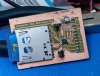
If you want to solder it into a breadboard or vector board, you could solder small wires (such as wirewrap wire) to each pad with a low power, pointed tip soldering iron, and deadbug it (mount it upside-down with the pads on top).
15watter from radio shack works beautifully. I filed the tip down to a nice size and it works great. i can soldierd to the tiniest of legs no prob with it.
One thing you have to be mindful of: does the large pad in the center of the chip need to be soldered down for heatsinking or grounding purposes? If so, you'll need to use a reflow method, because you obviously can't get under the chip with an iron. That's usually my biggest concern; damaging the chip during reflow by putting too much heat on it, while making sure it's soldered properly and maintaining alignment to the pads.
Solder paste + toaster oven is probably the most 'accessible' option for a hobbyist. Otherwise it is usually done with a hot air rework station in a professional environment (that's what our NASA certified techs do with those packages fwiw).
The picture below is from the sparkFun site. SparkFun used this method for production for a while, maybe a few years. I use a Teflon fry pan on a gas range (burner).
The bad thing about the method is that the glue that holds the copper to the PCB gets hotter then it would with an oven or hot air. It has not been a problem for me.
The good thing is that the parts do not get as hot as they would with an oven or hot air.
This is a fast process, maybe 3 minutes to heat till the solder reflows and what time it takes to cool.
This site uses cookies to help personalise content, tailor your experience and to keep you logged in if you register.
By continuing to use this site, you are consenting to our use of cookies.