Hi,
I am doing my first avr exp using a temp sensor LM35 to blink blue green or red led according to the temp of the room.
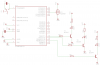
• Connected the leds to PORT B of atmega8L uC and temp sensor to ADC 3 input.
• Using internal oscillator 1MHz as clk, internal reference voltage of 2.56 as reference voltage in FREE RUNING MODE.
• ADLAR = 0 i.e. right adjusted.
• Connected a 0.1uF decoupling capacitor at VREF pin as per datasheet, “Internal 2.56V Voltage Reference with external capacitor at AREF pin”.
• Using prolight leds 1W (for good intensity), transistor in saturation with Ic around 10mA.
According to what I hv understood with temp sensor 10.0 mV/˚C scale factor, output voltage of sensor is input voltage of ADC …...
ADC = ( Vin * 1024 / Vref )
If room temp= 30˚C, Vin = 300mV = 0.3V, So ADC = (.3*1024/2.56)=120. So I hv divided the result by 4.
Fig b.png
IN ATTACHMENT AS A THUMBNAIL
Here is my code that I hv written in AVR Studio4
#include<avr\io.h>
int main (void)
{
unsigned int TEMP;
ADMUX= (1<<REFS1)| (1<<REFS0)| (1<<MUX1)| (1<<MUX0);
ADCSRA= (1<<ADEN)| (1<<ADFR);
DDRB|=0xFF;
while(1)
{
TEMP=ADCL+ADCH*256; // ADCH is read only to update ADC data register, otherwise no need
TEMP=TEMP/4;
if(TEMP<=20)
PORTB=1<<PB1; //BLUE
else if(TEMP>20&&TEMP<=28)
PORTB=1<<PB0; //GREEN
else if(TEMP>28&&TEMP<=35)
PORTB=1<<PB3; //RED
else
PORTB= ((1<<PB1)| (1<<PB0)| (1<<PB3));
}
}
But I don’t know what the problem is; uC only blinks the led which satisfies the minimum criteria for temp i.e. blue. Even if I multiply the final TEMP variable by 10000 and keep min temp criteria for blue led to blink as less than 2˚C, then also only blue led blinks. It seems the uC is taking no voltage as input.
I hv checked that if I write (PORTB=1<<PB0), then green led blinks or (PORTB=1<<PB3), then red led blinks instead of (PORTB=1<<PB1)
I have connected output pin of sensor directly to uC, is there a problem in it or do I need to use more decoupling capacitors somewhere in the circuit.
plz help
I am doing my first avr exp using a temp sensor LM35 to blink blue green or red led according to the temp of the room.
• Connected the leds to PORT B of atmega8L uC and temp sensor to ADC 3 input.
• Using internal oscillator 1MHz as clk, internal reference voltage of 2.56 as reference voltage in FREE RUNING MODE.
• ADLAR = 0 i.e. right adjusted.
• Connected a 0.1uF decoupling capacitor at VREF pin as per datasheet, “Internal 2.56V Voltage Reference with external capacitor at AREF pin”.
• Using prolight leds 1W (for good intensity), transistor in saturation with Ic around 10mA.
According to what I hv understood with temp sensor 10.0 mV/˚C scale factor, output voltage of sensor is input voltage of ADC …...
ADC = ( Vin * 1024 / Vref )
If room temp= 30˚C, Vin = 300mV = 0.3V, So ADC = (.3*1024/2.56)=120. So I hv divided the result by 4.
Fig b.png
IN ATTACHMENT AS A THUMBNAIL
Here is my code that I hv written in AVR Studio4
#include<avr\io.h>
int main (void)
{
unsigned int TEMP;
ADMUX= (1<<REFS1)| (1<<REFS0)| (1<<MUX1)| (1<<MUX0);
ADCSRA= (1<<ADEN)| (1<<ADFR);
DDRB|=0xFF;
while(1)
{
TEMP=ADCL+ADCH*256; // ADCH is read only to update ADC data register, otherwise no need
TEMP=TEMP/4;
if(TEMP<=20)
PORTB=1<<PB1; //BLUE
else if(TEMP>20&&TEMP<=28)
PORTB=1<<PB0; //GREEN
else if(TEMP>28&&TEMP<=35)
PORTB=1<<PB3; //RED
else
PORTB= ((1<<PB1)| (1<<PB0)| (1<<PB3));
}
}
But I don’t know what the problem is; uC only blinks the led which satisfies the minimum criteria for temp i.e. blue. Even if I multiply the final TEMP variable by 10000 and keep min temp criteria for blue led to blink as less than 2˚C, then also only blue led blinks. It seems the uC is taking no voltage as input.
I hv checked that if I write (PORTB=1<<PB0), then green led blinks or (PORTB=1<<PB3), then red led blinks instead of (PORTB=1<<PB1)
I have connected output pin of sensor directly to uC, is there a problem in it or do I need to use more decoupling capacitors somewhere in the circuit.
plz help
Attachments
Last edited:
")
