Please can anyone help with the following task.
I need to know the following
1.Why the output voltage and D.C. voltage has changed as the value of the capacitor has been reduced?
2.The changes in the output waveform?
Here is the task.
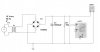
Task 7 Enter the above circuit into Multisim, initially set the value of the capacitor at 10,000μF and connect a 16Vrms, 50Hz ac sine-wave generator to the input of the bridge rectifier.
a. Obtain a print-out of the output waveform and the D.C. voltage for a capacitor value of 10,000μF capacitor.
b. Replace the 10,000μF capacitor with a 4700μF capacitor and obtain a print-out of the output waveform and d.c. voltage.
c. Replace the 4700μF capacitor with a 1500μF capacitor and obtain a print-out of the output waveform and D.C. voltage.
d. Analyse the effect of varying the value of the capacitor on the output waveform and D.C. voltage obtained from the circuit. Explain why the output voltage and D.C. voltage has changed as the value of the capacitor has been reduced.
e. Repeat a. to c. above with R1 set to 150 Ω and explain the changes in the output waveform.
I need to know the following
1.Why the output voltage and D.C. voltage has changed as the value of the capacitor has been reduced?
2.The changes in the output waveform?
Here is the task.
Task 7 Enter the above circuit into Multisim, initially set the value of the capacitor at 10,000μF and connect a 16Vrms, 50Hz ac sine-wave generator to the input of the bridge rectifier.
a. Obtain a print-out of the output waveform and the D.C. voltage for a capacitor value of 10,000μF capacitor.
b. Replace the 10,000μF capacitor with a 4700μF capacitor and obtain a print-out of the output waveform and d.c. voltage.
c. Replace the 4700μF capacitor with a 1500μF capacitor and obtain a print-out of the output waveform and D.C. voltage.
d. Analyse the effect of varying the value of the capacitor on the output waveform and D.C. voltage obtained from the circuit. Explain why the output voltage and D.C. voltage has changed as the value of the capacitor has been reduced.
e. Repeat a. to c. above with R1 set to 150 Ω and explain the changes in the output waveform.
Attachments
Last edited:
