Hello everyone,
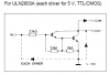
Just a quick comment on the LED circuit using the ULN2803 transistor array. The diodes isolate the transistor array from the Mega32. Since I am switching the ground pin on the ULN2803, the diodes prevent the chips from grounding through the MCU. Yes, switching the ground on the ULN2803 isn't proper but with the diodes in place it does work. That lamp has been running non-stop for over 2 years without a problem.
I wouldn't recommend this for other applications (certainly not commercial applications), but for this lamp it works.
The other option is to PWM the source voltage but the RGB LEDs have a common source pin so that wasn't possible.
You can slap my hand now
")
Eddy Wright
Wright Hobbies Robotics