Fintek
Member
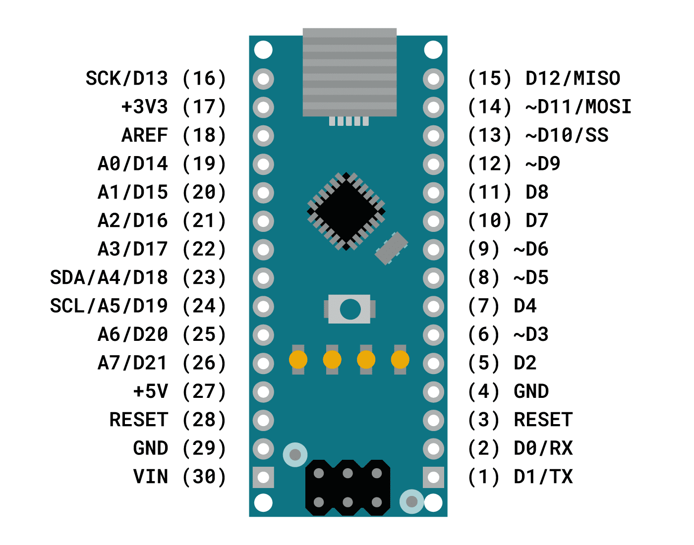
I am trying to get an Elegoo Nano to control a sound board through 4 pins by making them low one at a time, then a combination.
When it gets to sound four, it is supposed to blink the built in led four times, then make pin 22 low. Instead it gives a long blink, three short blinks, then turns on the TX and RX lights. Any idea what is going on? I've tried 3 new boards and they all do the same.
Here is the code:
void setup() {
pinMode(19,OUTPUT);
pinMode(20,OUTPUT);
pinMode(21,OUTPUT);
pinMode(22,OUTPUT);
pinMode(LED_BUILTIN,OUTPUT);
digitalWrite(19,HIGH);
digitalWrite(20,HIGH);
digitalWrite(21,HIGH);
digitalWrite(22,HIGH);
digitalWrite(LED_BUILTIN,LOW);
}
void loop() {
delay(2000);
digitalWrite(LED_BUILTIN,HIGH);
delay(500);
digitalWrite(LED_BUILTIN,LOW);
digitalWrite(19,LOW);
delay(3000);
digitalWrite(19,HIGH);
delay(2000);
digitalWrite(LED_BUILTIN,HIGH);
delay(500);
digitalWrite(LED_BUILTIN,LOW);
delay(500);
digitalWrite(LED_BUILTIN,HIGH);
delay(500);
digitalWrite(LED_BUILTIN,LOW);
digitalWrite(20,LOW);
delay(2000);
digitalWrite(20,HIGH);
delay(2000);
digitalWrite(LED_BUILTIN,HIGH);
delay(500);
digitalWrite(LED_BUILTIN,LOW);
delay(500);
digitalWrite(LED_BUILTIN,HIGH);
delay(500);
digitalWrite(LED_BUILTIN,LOW);
delay(500);
digitalWrite(LED_BUILTIN,HIGH);
delay(500);
digitalWrite(LED_BUILTIN,LOW);
digitalWrite(21,LOW);
delay(2000);
digitalWrite(21,HIGH);
// problem seems to start here
delay(2000);
digitalWrite(LED_BUILTIN,HIGH);
delay(500);
digitalWrite(LED_BUILTIN,LOW);
delay(500);
digitalWrite(LED_BUILTIN,HIGH);
delay(500);
digitalWrite(LED_BUILTIN,LOW);
delay(500);
digitalWrite(LED_BUILTIN,HIGH);
delay(500);
digitalWrite(LED_BUILTIN,LOW);
delay(500);
digitalWrite(LED_BUILTIN,HIGH);
delay(500);
digitalWrite(LED_BUILTIN,LOW);
digitalWrite(22,LOW);
delay(2000);
digitalWrite(22,HIGH);
// starts working normally again
delay(2000);
digitalWrite(LED_BUILTIN,HIGH);
delay(500);
digitalWrite(LED_BUILTIN,LOW);
delay(500);
digitalWrite(LED_BUILTIN,HIGH);
delay(500);
digitalWrite(LED_BUILTIN,LOW);
delay(500);
digitalWrite(LED_BUILTIN,HIGH);
delay(500);
digitalWrite(LED_BUILTIN,LOW);
delay(500);
digitalWrite(LED_BUILTIN,HIGH);
delay(500);
digitalWrite(LED_BUILTIN,LOW);
delay(500);
digitalWrite(LED_BUILTIN,HIGH);
delay(500);
digitalWrite(LED_BUILTIN,LOW);
digitalWrite(19,LOW);
digitalWrite(21,LOW);
delay(2000);
digitalWrite(19,HIGH);
digitalWrite(21,HIGH);
delay(2000);
digitalWrite(LED_BUILTIN, HIGH);
digitalWrite(19,LOW);
delay(1000);
digitalWrite(19,LOW);
digitalWrite(20,LOW);
digitalWrite(21,LOW);
digitalWrite(19,HIGH);
digitalWrite(20,HIGH);
digitalWrite(21,HIGH);
delay(1000);
digitalWrite(LED_BUILTIN,LOW);
delay(1000);
}
When it gets to sound four, it is supposed to blink the built in led four times, then make pin 22 low. Instead it gives a long blink, three short blinks, then turns on the TX and RX lights. Any idea what is going on? I've tried 3 new boards and they all do the same.
void setup() {
pinMode(19,OUTPUT);
pinMode(20,OUTPUT);
pinMode(21,OUTPUT);
pinMode(22,OUTPUT);
pinMode(LED_BUILTIN,OUTPUT);
digitalWrite(19,HIGH);
digitalWrite(20,HIGH);
digitalWrite(21,HIGH);
digitalWrite(22,HIGH);
digitalWrite(LED_BUILTIN,LOW);
}
void loop() {
delay(2000);
digitalWrite(LED_BUILTIN,HIGH);
delay(500);
digitalWrite(LED_BUILTIN,LOW);
digitalWrite(19,LOW);
delay(3000);
digitalWrite(19,HIGH);
delay(2000);
digitalWrite(LED_BUILTIN,HIGH);
delay(500);
digitalWrite(LED_BUILTIN,LOW);
delay(500);
digitalWrite(LED_BUILTIN,HIGH);
delay(500);
digitalWrite(LED_BUILTIN,LOW);
digitalWrite(20,LOW);
delay(2000);
digitalWrite(20,HIGH);
delay(2000);
digitalWrite(LED_BUILTIN,HIGH);
delay(500);
digitalWrite(LED_BUILTIN,LOW);
delay(500);
digitalWrite(LED_BUILTIN,HIGH);
delay(500);
digitalWrite(LED_BUILTIN,LOW);
delay(500);
digitalWrite(LED_BUILTIN,HIGH);
delay(500);
digitalWrite(LED_BUILTIN,LOW);
digitalWrite(21,LOW);
delay(2000);
digitalWrite(21,HIGH);
// problem seems to start here
delay(2000);
digitalWrite(LED_BUILTIN,HIGH);
delay(500);
digitalWrite(LED_BUILTIN,LOW);
delay(500);
digitalWrite(LED_BUILTIN,HIGH);
delay(500);
digitalWrite(LED_BUILTIN,LOW);
delay(500);
digitalWrite(LED_BUILTIN,HIGH);
delay(500);
digitalWrite(LED_BUILTIN,LOW);
delay(500);
digitalWrite(LED_BUILTIN,HIGH);
delay(500);
digitalWrite(LED_BUILTIN,LOW);
digitalWrite(22,LOW);
delay(2000);
digitalWrite(22,HIGH);
// starts working normally again
delay(2000);
digitalWrite(LED_BUILTIN,HIGH);
delay(500);
digitalWrite(LED_BUILTIN,LOW);
delay(500);
digitalWrite(LED_BUILTIN,HIGH);
delay(500);
digitalWrite(LED_BUILTIN,LOW);
delay(500);
digitalWrite(LED_BUILTIN,HIGH);
delay(500);
digitalWrite(LED_BUILTIN,LOW);
delay(500);
digitalWrite(LED_BUILTIN,HIGH);
delay(500);
digitalWrite(LED_BUILTIN,LOW);
delay(500);
digitalWrite(LED_BUILTIN,HIGH);
delay(500);
digitalWrite(LED_BUILTIN,LOW);
digitalWrite(19,LOW);
digitalWrite(21,LOW);
delay(2000);
digitalWrite(19,HIGH);
digitalWrite(21,HIGH);
delay(2000);
digitalWrite(LED_BUILTIN, HIGH);
digitalWrite(19,LOW);
delay(1000);
digitalWrite(19,LOW);
digitalWrite(20,LOW);
digitalWrite(21,LOW);
digitalWrite(19,HIGH);
digitalWrite(20,HIGH);
digitalWrite(21,HIGH);
delay(1000);
digitalWrite(LED_BUILTIN,LOW);
delay(1000);
}


