Continue to Site

Welcome to our site!

Electro Tech is an online community (with over 170,000 members) who enjoy talking about and building electronic circuits, projects and gadgets. To participate you need to register. Registration is free. Click here to register now.

  • Welcome to our site! Electro Tech is an online community (with over 170,000 members) who enjoy talking about and building electronic circuits, projects and gadgets. To participate you need to register. Registration is free. Click here to register now.

apperance of a diode vs resistor

Status
Not open for further replies.

skippie101

New Member
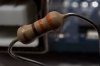
I am trying to find what the physical apperance of a diode is to a resistor. My understanding is that they both have colored bands on them, so how would I be able to tell which is which just by looking at them.
Any help is greatly appreciated.
 
Diodes almost never have color bands.
 

Attachments

  • resistor.jpg
    resistor.jpg
    13 KB · Views: 105
  • diode.jpg
    diode.jpg
    36 KB · Views: 116
...but some do!

Generally, though, a diode has only one stripe; a black stripe at the cathode end.

Alec
 

Attachments

  • Diodes.gif
    Diodes.gif
    36.3 KB · Views: 115
diode identification

...but some do!

Generally, though, a diode has only one stripe; a black stripe at the cathode end.

Alec


Thank you Alec and Ron,

Alec the pic of the diodes you posted look like some on the circuit board I have execpt with just the one stripe on the cathode side. Since they are glass and I can see the connecting wire inside I thought they were in-line fuses.
Thanks for the pic.
 
Thanks Ron for the pics of both the Resistor and Diode. I posted a reply to you earlier but does not look like it posted for some reason. I am new to the site and perhaps I need to get familiar with the operation.
Thanks again.
Paul
 
As you seem to be discovering, diodes generally speaking come in two flavors:

1. A small glass package (small signal diodes like the 1N4148 and small zeners), which has a single stripe indicating the cathode end.
2. A black plastic package, also with a stripe (generally white) indicating cathode.

Of course, diodes come in all sorts of weird packages, including ones that look like "flat-pack" resistors, DIPs, etc. But most are like the two styles above.
 
Yes, you are so right. As I have started visually scanning the circuit board, I have been seeing the different ones there are.
I have also found some rectifiers that are black plastic rectangle package approx. 1"x2" that house serveral diodes.
Thanks for your post.
 
Some resistors (that I've seen - maybe they were older, but they also seemed like they might have been higher accuracy?) can be in a metal "tube", with the value and other information printed on them (they almost look like small axial lead electrolytics without the plastic outerwrap); something else to keep in mind is that some inductors look like standard resistors (albeit generally not in the "dumbbell" shape, but rather cylindrical with the value stripes). Then of course there are the large wattage resistors (and diodes, too) with integrated finned heatsinks (you generally won't find these on a PCB, though). :)
 
Thanks cr0sh,

If you didn't tell me resistors came in metal tubes, I would have seen them as Capacitors, especially if there was writting on the side instead of colored bands.
No heatsinks on this PCB.
I am just trying to get my Reel to Reel player operating correctly. Nothing earth shaking, like high voltage or big. I have been looking at the schematic and just now understanding a bit more than I did before. Even though I can actually tell what is what and where it is on the circuit board, it will not really help me unless I can test the parts correctly.
 
I have also found some rectifiers that are black plastic rectangle package approx. 1"x2" that house serveral diodes.

Those are probably bridge rectifiers (4 diodes in a package), with 4 connections. Package is probably marked "~ + - ~" (outer pins are AC, inner DC).
 
Those are probably bridge rectifiers (4 diodes in a package), with 4 connections. Package is probably marked "~ + - ~" (outer pins are AC, inner DC).

Yes, that is exactly what the marking are. There are 4 of them through out the PCB, 2 of them have a small red dot on one end of the pakage. So, these would change AC current to DC current?
 
Yes, that is exactly what the marking are. There are 4 of them through out the PCB, 2 of them have a small red dot on one end of the pakage. So, these would change AC current to DC current?

Let me ask you a question, how would I be able to check this using a standard digital multimeter?

Thanks.
 
Status
Not open for further replies.

Latest threads

New Articles From Microcontroller Tips

Back
Top