Electro Tech is an online community (with over 170,000 members) who enjoy talking about and building electronic circuits, projects and gadgets. To participate you need to register. Registration is free. Click here to register now.
Welcome to our site! Electro Tech is an online community (with over 170,000 members) who enjoy talking about and building electronic circuits, projects and gadgets. To participate you need to register. Registration is free. Click here to register now.
Does anyone know of any free or reasonably priced power electronics simulation software to enable me to simulate a DC to AC Inverter. I've found loads of free software but none for this purpose.
Does anyone know of any free or reasonably priced power electronics simulation software to enable me to simulate a DC to AC Inverter. I've found loads of free software but none for this purpose.
Just downloaded it eric looks good, thanks a lot now if I can learn how to use it quickly then I can use this for my project instead of building and seeing as I don't have practical experience of building electronic projects then I'll be on a winner. Also I'll easily be able to design different types of circuit, so you are a life saver cheers
Pommy I already had swcadIII it had no transformer among the components so it was no good, however although the message before downloading was that I already had swcadIII I downloaded it anyway and miraculously it has a transformer now not sure how good it is though I'll decide between the two what is best but thanks to you both. It's all in my own hands now I don't need to rely on anybody to help me build a circuit.
So thanks a million to you both
Simulation software won't show what happens when your transformer has resistance in its windings that causes voltage loss, and inductance and capacitance that create voltage spikes.
It won't show you what will blow up when the transistors have less current gain than typical.
you always make me feel so happy Uncle Scrooge, you know how to cheer me up.
Eric I was wondering if you have any tips on using the software as it's really mind blowing to me just now and I'm running out of time until my deadline on the 9th may. For example how do you designate a resistor as the load resistor so as the simulation knows where your output is supposed to be (or how do you designate the sampling point) and the other thing I can't fathom is how to select a centre tapped transformer.
James,
Did you copy an existing inverter's circuit or design one yourself?
I hope it is not the defective inverter circuit from Aaron Cake's site.
If you attach its schematic then we can tell you if we made it and any problems it might have.
Uncle Scrooge doesn't use a lot of words but the ones he does use are usually correct. I've learned that ignoring them can result in breathing smoke.
Eric I was wondering if you have any tips on using the software as it's really mind blowing to me just now and I'm running out of time until my deadline on the 9th may. For example how do you designate a resistor as the load resistor so as the simulation knows where your output is supposed to be (or how do you designate the sampling point) and the other thing I can't fathom is how to select a centre tapped transformer.
The simulator doesn't care what the output it; it's just whatever you decide to use as the output. I've attached an example to show you how I've done it. Note that I only think this is correct; seems to be to me. I'm sure I'll be corrected if not.
Oh yes: you can name wires (nodes) by pressing F4 and typing in a name, then placing the name on the wires as if you were adding any other component. Then when you run the simulation and select that node to trace it will be called (i.e.) 'V(out)' instead of something non-descriptive like 'V(004)'.
That does help a little but with swcadIII I always get messages about nodes etc plus I don't think it actually has a transformer only something called a common mode noise suppressor that I thought looked like one but I've never heard it called that.
Well uncle scrooge the circuit I've chosen as my circuit is this **broken link removed** which is fine but I need another example to achieve a pass and another two to achieve an A grade. I am considering just using the other link **broken link removed** although I cant explain fully what is happening with sn7400, I might have to bluff it and I could invent one or two maybe without having any idea if they will work. I think I could explain one on the basis of a capacitor charging and discharging through a resistor to set the frequency of which a dc current flows in opposite directions clockwise and anticlockwise across the primary of a transformer inducing an ac current in the secondary.
What do you think Uncle scrooge? The important thing is not that they will work but just that in theory it could be made to work. I'm an electrical engineer so I guess they will make allowances seeing I don't have the in depth knowledge expected of an electronics student.
Hi James,
It is too bad you found fairly old and complicated inverter circuits that use all Japanese parts.
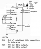
The inverters have a very simple circuit that produces a square-wave output. Many electronic products won't work with a square-wave because its peak voltage is 70% of the peak voltage of a sine-wave that they expect.
The first circuit uses 4 Mosfets because its transformer does not have a center-tap like in nearly all inverter circuits and like in the second circuit. It needs only two N-channel Mosfets if it has a center-tapped transformer.
The "Performance Evaluation" shows its poor performance.
Without a load its output voltage is 10% high.
With a 60W load its output voltage is correct.
With a 140W load its output voltage is 10% low.
Fake it. Don't show the old TTL gate IC. Don't show the lousy performance. Don't show the all Japanese parts. Don't show the "bandaid" of using 4 Mosfets because the wrong transformer was used.
Happy now?
so this circuit is easily improved upon by using another version of the 4069UB and a centre tapped transformer with two drive transistors and only two mosfets.
do all 4069UB operate with the same principle, is that principle that the inverter supplies each drive transistor (2SC1815) with a square wave which will be in anti-phase for each in order to make the two mosfets become forward bias at a 180 degree phase difference ensuring they operate at different times.
If my assumption of this is correct then if I use only two mosfets a p and n type then it wont be necessary to ensure that the (divided) square wave signal feeding the two mosfets are each in anti phase with one another, is that a correct guess. I'm assuming that a p and n type have opposite requirements to make them forward bias one high and one low but that sounds a bit like crap to me.
Any chance someone could explain the difference of operation between an ordinary transformer winding and a centre tapped one. Does the centre tapped one recieve current through the centre tapping which then goes left or right depending upon where it came from creating an alternating flux and inducing an ac signal on the secondary ?
There are many ways to make a square-wave oscillatior. These two circuits use digital inverters or gates plus many resistors and capacitors.
A CD4047 IC is an RC oscillator plus a digital divider. It has two outputs that have "perfect" 50-50 duty-cycle square-waves that are 180 degrees apart and are perfect for driving two N-channel Mosfets that drive a center-tapped transformer. It uses a single resistor and a single capacitor.
The center-tap is connected to +12V and each opposing end connects to the drain of a power Mosfet or the collector of an old power transistor. The Mosfets or transistors are driven to ground in opposition which creates a high current square-wave in the transformer.
The transformer without a center-tap needs push-pull drivers at each end of the winding so that AC flows. One wire is driven to +12V while the other wire is driven to 0V, then they reverse.
Thanks a lot Uncle scrooge, I don't see how I can fail this now. I found this datasheet https://www.electro-tech-online.com/custompdfs/2008/04/cd4047b.pdf I've not completely understood everything but I will get to grips with it. I'm making two assumptions from what I've understood so far and that is that seeing as you mentioned the 50-50 duty cycle it will be operating in monostable mode. So this would mean from what I understand from what I've read about them is that they have one stable mode which they will revert back to after a period of time, then they require a pulse trigger to begin a new cycle to enable the duty cycle to be controlled. I don't know if that is correct but I'm assuming it is so I'm wondering about the source of this pulse, my first initial thought about it was that it had to be an external pulse but I think maybe the component is self regulating if you know what I mean it requires no external stimulus as long as you connect the pins together in the right way, I'm guessing just now, I need to learn a bit more about these pin out connections I guess bcos I don't know much about that sort of thing but I'm sure it's done very easily its a bit mind blowing at the moment thanks the help, I've a week to work everything out.
Thanks again you may just have altered history.
I'm making two assumptions from what I've understood so far and that is that seeing as you mentioned the 50-50 duty cycle it will be operating in monostable mode.
There are many ways to make a square-wave oscillatior. These two circuits use digital inverters or gates plus many resistors and capacitors.
A CD4047 IC is an RC oscillator plus a digital divider. It has two outputs that have "perfect" 50-50 duty-cycle square-waves that are 180 degrees apart and are perfect for driving two N-channel Mosfets that drive a center-tapped transformer. It uses a single resistor and a single capacitor.
The center-tap is connected to +12V and each opposing end connects to the drain of a power Mosfet or the collector of an old power transistor. The Mosfets or transistors are driven to ground in opposition which creates a high current square-wave in the transformer.
The transformer without a center-tap needs push-pull drivers at each end of the winding so that AC flows. One wire is driven to +12V while the other wire is driven to 0V, then they reverse.
I made this circuit but I faced an strange problem. I am not able to see 180 degree of phase shift between pins 10 and 11 of 4047! both are the same when I look then by my scop! My scop is a one channel and I just see the below square wave but not to be inverted in the other pin (both are at the same place/position while I do not change anything on the scop)!! It is very strange.
Another question Which I have regarding to this ,
I want to know how much of freq stability it has?
The datasheet for the CD4047 says that its has a true output and a complement output.
They are 180 degrees from each other. When one goes high then the other goes low.
You must use a dual beam 'scope to see it.
The datasheet has a typical graph that shows the frequency changing when the supply voltage changes when the timing resistor has a low value and the frequency barely changes when the timing resistor has a high value.
The datasheet has a typical graph that shows the frequency changing when the temperature changes at different supply voltages.
The datasheet has a typical graph that shows the frequency changing when the value of the timing capacitor is changes at different supply voltages.
So you can pick the amount of stability.
This site uses cookies to help personalise content, tailor your experience and to keep you logged in if you register.
By continuing to use this site, you are consenting to our use of cookies.


")

 not sure how good it is though I'll decide between the two what is best but thanks to you both. It's all in my own hands now I don't need to rely on anybody to help me build a circuit.
 until my deadline on the 9th may. For example how do you designate a resistor as the load resistor so as the simulation knows where your output is supposed to be (or how do you designate the sampling point) and the other thing I can't fathom is how to select a centre tapped transformer.
")