Continue to Site

Welcome to our site!

Electro Tech is an online community (with over 170,000 members) who enjoy talking about and building electronic circuits, projects and gadgets. To participate you need to register. Registration is free. Click here to register now.

  • Welcome to our site! Electro Tech is an online community (with over 170,000 members) who enjoy talking about and building electronic circuits, projects and gadgets. To participate you need to register. Registration is free. Click here to register now.

anyone Know About It

Status
Not open for further replies.

Eplanet

New Member
hello to all
please tell what is different between analogue Ground and digital Ground?
thanks Eplanet
 
Eplanet said:
hello to all
please tell what is different between analogue Ground and digital Ground?
thanks Eplanet

If a circuit uses both analog and digital signals (ie a microcontroler with an AD converter, or an audio amplifier with some sort of digital control) it is a good design practice to separate the grounds of both parts of the circuit.

That way, the noise that digital circuits ussually generate doesn't "get into" the analog circuits, where it may be amplified.

The reference of the analog part is called "Analog Ground",

The reference of the digital part is called "Digital Ground"​

They should be kept apart from each other, and should be joined only at a single point (ussually the power supply's output)
 
hi suppose we have one circuit that was combination of Analog and digital circuits and these components(digital and analog) have some separate Ground. how can i make digital Ground and how can i make analog Ground? foe example if digital circuit work with 5v and analog circuit work with 5v and i have only one power supply(5v) in this circuit what can i do for producing different Ground?
thanks Eplanet
 
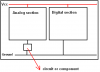
The ground isn't actually different, it's simply physically seperate. So instead of attaching the two grounds right at the different circuits you run seperate ground lines from each chip to the power supply. If you really must you can simply connect analog and digital grounds to the system ground at the same point close to the chip, but this isn't going to provide any degree of noise immunity.
 
Analog ground and digital ground are just expressions that simplify the objective of knowing (and controlling) where your (ground) current flows.

Further this simplification, you generally worry that digital ground currents might upset the ground potential of analog signals. The simplest way to minimize this upset is to prevent (digital) currents from flowing in the analog ground path.
 
hi
Digital circuits may have spikes and high-frequency noise that can propagate into analog circuits if care is not taken.
as result if we connecting all Ground with together then digital noises can effect to analog circuit.
i want to know that how can i separate these Grounds and keep in mind that i have one PS (one Ground line) in circuit.
is there any component that can separate these Grounds?
 
Eplanet said:
is there any component that can separate these Grounds?

Yes, it's called a PCB - they BOTH have to be joined together, because they are the same thing - but they are listed seperately so you can design your PCB to prevent the digital noise entering the analogue side via currents in the ground connections.
 
Eplanet said:
hi
Digital circuits may have spikes and high-frequency noise that can propagate into analog circuits if care is not taken.

Goto www.analog.com search for AN214, it covers grounding rules.
 
Ground Tale

hello all
what do you thinking about this attachment for more clearly?
is there any circuit or component that before connecting Ground to analog section that can preventing digital noise to analog section?
Eplanet
 

Attachments

  • Ground Tale.PNG
    Ground Tale.PNG
    5.7 KB · Views: 202
Status
Not open for further replies.

Latest threads

New Articles From Microcontroller Tips

Back
Top