Hi
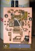
Im making a small wireless FM receiver based on RF solutions pair of recievers/transmitters at 433 MHz.
Until now ive just been using a 17.5 cn length of cable as an antenna with good results but for production im not sure if it is a good idea to continue with this method.
How easy/difficult is it to encorporate the antenna into the PCB tracks of the PCB. I can find maybe a square inch to play with on the board. Is there alot of calculations/fine tuning required or sould i just be able to make a track say 17.5 cm long that may double back on its self to fit on the board (the board is approx 9 cm long.
Any thoughts?
Justin