Dear All,
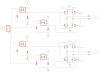
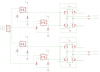
Thanks in advance for your patience, I'm still a newbe. I recently purchased on the cheep a Vexta PK244-01AA Stepper motor that I want to use in bipolar mode. Since the current for the ultimate bipolar stepper that I want to purchase requires 4 Amps per phase, I decided that a L298 or L293D would be inadequate for my needs and decided to design a discreet driver for use with a Arduino uC board with 5V/100mA outputs. I am particularly concerned with my component choices since I have never done this before. I chose the **broken link removed** opto-isolator to bring my logic levels to 24V so that I could control the H-bridge. I chose the FJAF4x10YTU PNP/NPN transistors because of their cost/current handling ability. I chose the 1N4148TA diodes because of their low t(RR). Would someone be kind enough to look at my schematic and let me know if it all makes sense or if there are other choices that should be made instead or if there are out-in-out errors.
Thanks,
DavidBear
") you can check the rest of their products. they do have some dips and more basic drivers.
you can check the rest of their products. they do have some dips and more basic drivers.