thermistor circuit
hi,
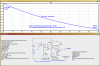
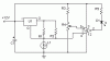
in the circuit attached could any1 plz tell me what are these caliberation and zero pots for, what is thier purpose in the circuit?
i did use 1k fine trim pots when i built this circuit but i dint get any result, and where should the output voltage be measured? is it at point U?
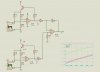
i am not able to obtain output for any of the circuits plz if any1 has a circuit that works plz help!
hi,
in the circuit attached could any1 plz tell me what are these caliberation and zero pots for, what is thier purpose in the circuit?
i did use 1k fine trim pots when i built this circuit but i dint get any result, and where should the output voltage be measured? is it at point U?
i am not able to obtain output for any of the circuits plz if any1 has a circuit that works plz help!
")
") )
) 