Continue to Site

Welcome to our site!

Electro Tech is an online community (with over 170,000 members) who enjoy talking about and building electronic circuits, projects and gadgets. To participate you need to register. Registration is free. Click here to register now.

  • Welcome to our site! Electro Tech is an online community (with over 170,000 members) who enjoy talking about and building electronic circuits, projects and gadgets. To participate you need to register. Registration is free. Click here to register now.

Analyzing an op amp circuit

Status
Not open for further replies.
It's not from a textbook. It's from a book compiled by one of our lecturers. He expects us to learn everything ourselves so I'm trying.
To find the amplitude at the junction, do you first need to find out the current?

Jason M

hi,

You dont need the current, its a voltage divider

Vjunction = Vpin6 * (Xc/[ Xc +100R]) ; where Xc =159R

E
 
I got the voltage at the juction to be -0.65V. Is this the amplitude of the wave?


hi J,

As you have calculated the Xc value, you have now to apply the complete formula for the divider.

Vout=Vin*xC/sqrt(xC^2+R^2)

Which is Vout = 1.1 * 159/ sqrt( 159^2 + 100^2)

When you have worked out the value, you will see at 1KHz the filter has only a marginal effect upon the amplitude, post your value.

Next we will cover the Vout waveform plot.

E.
 
Hello there guys,

I took a look at the circuit and i agree that with no positive source limitation the output would go up to 23.9 volts, so you guys analyzed this circuit pretty well :)

Now with the positive source limited to 9v it's an entirely different story. It's very hard to analyze as Eric says and this is where we get into muddy water where we have to know other constraints in order to really figure this out, and what that boils down to (as is often the case) is knowing what the instructor expects and what his/her assumptions are about 741 op amps. There are several ways to handle this. Let me give a few examples and then throw out some guesses...

Assuming the output clamping effect is to be acknowledged:
1. A 741 output goes up to the power supply voltage and then gets clamped.
2. The 741 op amp output can go up to the positive rail minus x volts (like 1v, 1.5v, 2v, etc.).
In the above case we would still have to do the math, and we'd get different answers for each case. For the sine plot we'd see a sine wave that gets clamped somewhere around 9v depending on what we take to be the clamping voltage (1 or 2 above, and there are several cases for 2 above).

Assuming there is no clamping:
1. Calculate the output as if there was no clamping voltage limit.

Now for the guesses :)

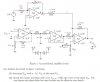
I am guessing that the 10k resistor between pin 6 of the second stage on the bottom and pin 2 of the last stage on the bottom is really supposed to be 100k. That would make the total current into the last stage a nice neat 40ua, which together with the gain and offset would give us a nice neat +5v output.

My recommendation is to try to contact the instructor and ask about the possible problem that came up. If you cant do that, then change that 10k to 100k and do the analysis over again.

It really depends where you are in the course work that would tell us more about how to proceed, as that would tell us how theoretical we can be and how practical we must be.

We can look closer at the AC response once we resolve these issues for the DC response.
 
Hi,

I think the 10k is correct even though we get a higher value than possible. I think they are trying to teach us the difference between an ideal situation and the real-life situation. I will however try and find out if there is a mistake. Otherwise assume this as correct.

Jason M
 
Hello,

Ok, well if it is correct then you have to assume that the output of the 741 clips at some point, and to get that value you have to look at the data sheet and try to determine what value of clipping level you want to use. For a few examples:
1. The op amp clips at the exact power supply level of 9v (more theoretical than real)
2. The op amp clips at the power supply level minus 1 volt (that would put it at 8v)
3. The op amp clips at the power supply level minus 1.5 volts (that would put it at 7.5v)
4. Etc., etc....

Alternately, you could show this as the power supply drop minus an unspecified voltage, say Vclip. That way when you draw the output waveform you'll show the sine going up and down as usual, but when it goes up you'll show it being clipped at "Vclip" rather than 9v or 8v or whatever.

So you'll have to find out more information or just decided what you want to do here.
 
Hi,

I calculated Vout to be 0.93V.

hi J,
Thats close enough.;)

Have you tried to plot the Vout waveform as required in Part2 of the problem.?

Post a diagram of what you think it will look like, we can check it out.

As you can see the drop from 1.1Vppk to 0.93Vppk will only have a small effect upon the Vout waveform.

E.
 
0.93Vppk means the amplitude will be 0.465? Do i need to calculate the wavelength? Period, etc?or just draw it?
 
0.93Vppk means the amplitude will be 0.465? Do i need to calculate the wavelength? Period, etc?or just draw it?

hi,
The 0.93V peak to peak is at the junction of 100R and 1uF, you still have to amplify it by 10 times via Amp 'D', also the 2Vdc on the non inverting input amplified by 12 and the -0.9Vdc .

A 0.93V pk to pk is a 0.465V peak.

The period t= 1/ 1KHz .

Hint: the Vout will be in positive saturation most of the period

Draw and post it, we can help from that, dont worry if you get it wrong the first time you do it.:D

E.

EDIT:

This image is the waveform at the junction of the 100R and 1uF.....................NOT the 'D' Vout
 

Attachments

  • AAesp01.gif
    AAesp01.gif
    10.7 KB · Views: 260
Last edited:
Hi again,


Hold on a sec here, are we starting with a 0.1v peak input or is that peak to peak?

If it is peak, then the output is also calculated in peak volts. So for a 0.1v peak input we get 1.1v peak output of the first stage, then multiplied by the filter factor at 1kHz of about 0.85 we get close to 0.935v peak which is close to 0.93 volts peak.

If the 0.1v is a peak to peak measurement, then the output of the op amp is also peak to peak and the final output is 0.93 peak to peak approximately.

So the units ('peak' or 'peak to peak' volts) follow through from input to output.
 
Hold on a sec here, are we starting with a 0.1v peak input or is that peak to peak?
Morning Al,

The bottom line of text on the OP's original circuit states 0.1V p-p at 1KHz sine.

E.
 

Attachments

  • Circuit_2.jpg
    Circuit_2.jpg
    57.1 KB · Views: 258
Hi,

Ok thanks Eric. Just wanted to make sure this was all clear :)
 
For part i we were suppose to analyse the circuit and Vout was 23.9V. This was just a demonstration of an ideal op amp however the maximum output is around 7.5 volts, so we are suppose to find a way to make the circuit realistic which would be changing the 10k just before amp D to a 100k producing an output of 5V which is more realistic.

For part ii using the given circuit, I calculated Vp-p to be 0.930V. Using the formula V2=(V1xR1)/(R1+R2) to calculate the DC i got 12.9V.
I found Vout to be: Vout = Vac Sinw + Vdc =(-4.65V) sinw +12.9V.

Is this correct?
 
Hi J,

Hint #1
Consider that Vin is 0V.
Calculate Vout with just the -0.9V and +2Vdc inputs to 'D', [Vin at 0v] assume for this calculation that the OPA supply is +/- 25Volts.

Your answer of +12.9V is correct.

Hint #2.
Now consider the -0.9V and the +2V are now 0Volts, calculate Vout for just the amplified 0.93 Vppk sine wave [ that should be easy, 10 * 0.93]

Your answer for the 100mVppk , Vout =+/-4.65V is correct.

Now add algebraically the values from Hint #1 and Hint #2, use graph paper, post your results.

Hint #3.
As the Vout is at +12.9V due to the two DC inputs, with the Vin at 0V.

Calculate the Vout minimum and Vout maximum when you add algebraically the +4.65V and -4.65V to the +12.9V value.

Dont forget the 741 will saturate at around +8V.

Post your final calculation.

E.
 
Status
Not open for further replies.

New Articles From Microcontroller Tips

Back
Top