Continue to Site

Welcome to our site!

Electro Tech is an online community (with over 170,000 members) who enjoy talking about and building electronic circuits, projects and gadgets. To participate you need to register. Registration is free. Click here to register now.

  • Welcome to our site! Electro Tech is an online community (with over 170,000 members) who enjoy talking about and building electronic circuits, projects and gadgets. To participate you need to register. Registration is free. Click here to register now.

Analogue AC Over Voltage switch

Status
Not open for further replies.

Augustinn

New Member
This one may sound easy, but ..
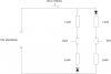
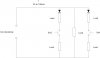
I'm looking to build very low power (300mW max) AC switch which will switch off at preset AC voltage. This has to happen in all AC quadrants which means switch has to turn on at same voltage on falling edge as well (SCR if out). For example:
IF Vac < 50V THEN SW1=ON
IF 50V < Vac THEN SW1=OFF
IF Vac > (-50V) THEN SW2=ON
IF (-50V) > Vac THEN SW1=OFF

This would not be a difficult if There is an option to use DC ICs (Opamp, Comp etc). However, this has to run purely on AC. No DC components. Any suggestions?
 

Attachments

  • AC underwoltage switch.jpg
    AC underwoltage switch.jpg
    27.6 KB · Views: 193
I don't understand the purpose of your schematic with the two diodes, four loads and two switches. In that diagram you are switching halfwave rectified DC, yet you are talking about switching AC in all four AC quadrants with SW1 and SW2.
What is the ultimate goal of your project? ie: Is it a light dimmer, motor control, etc?
 
There are two groups of independent loads, one for quadrants 1 and 2 and second for quadrant 3 and 4. They are unipolar loads and therefor there is a reason for rectifier diodes. Even if it should not matter, switch is between loads. Project is a load balancer with over voltage shutdown. One thing I did not mention is that loads are variable.
 
The circuit won't work as you described.

All you have is two half-wave rectifiers with switches connected to the loads.

The loads won't receive a steady 50VDC but pulses of 120√2 = 170V. The RMS voltage across each load will be 60V so if they're two resistive loads that can handle 60V it won't matter, if they're active loads (they have transistors and diodes), it will matter, they'll blow up.

Rectifier - Wikipedia, the free encyclopedia
**broken link removed**
 
Actually it does work quite well with MCU on board (PIC12) which senses Vin and turning on and off at predefined voltages. Of course what yo see is not whole circuit. I agree with you about two rectifiers. Each one should work only in Pos oe Neg quadrants. I modified a drawing a bit to get closer to real circuitry.
My question is if there is some analogue, low power solution for this circuit. SCR, Triac or Sidac will not work due to theirs high power, quadrant asymmetric nature. Any ideas?
 

Attachments

  • AC voltage switch 2.jpg
    AC voltage switch 2.jpg
    31 KB · Views: 185
How about posting the rest of the circuit?

Sorry but what you've said so far doesn't make much sense.
 
What does not make sense? Turning loads on and off at preset voltages? Take it this way, load which is always on (middle one) is neither resistive neither capacitive. Current wave is perfectly in phase, but the PF is very low, as low as 0.4. It peaks at 90 and 270 degrees but there is no draw if Vac is lover as 50 - 60V. Passive PFC front end is not very practical solution because there is no full wave rectifier so you have to go with large L and C directly on primaries. My working solution is what I call Load balancer. You insert loads which will work as a resistive load but only from lets say [0 - 60] AND [120 - 180] AND [180 to 240] AND [300 to 360] degrees. However, I had to do it with PIC controller, which is not very practical either. What I would like to achieve is slow acting, analogue solution.
 
Are you try to make a power factor compensation circuit?
 
If this is a PFC for a power supply, there are chips designed for this purpose already. Basically they use a special boost converter right after the rectifier to charge the first filter cap to keep the input AC voltage & current in phase. The best type of PFC circuit depends on the load. What is the load which you want to PFC?
 
Last edited:
PFC controller is not an option. As I mentioned before, it has to be analogue solution and there is no full bridge rectifier in the circuit. PFC requires heavy magnetics and PFC IC do require DC Vin.
 
Status
Not open for further replies.

Latest threads

New Articles From Microcontroller Tips

Back
Top