Continue to Site

Welcome to our site!

Electro Tech is an online community (with over 170,000 members) who enjoy talking about and building electronic circuits, projects and gadgets. To participate you need to register. Registration is free. Click here to register now.

  • Welcome to our site! Electro Tech is an online community (with over 170,000 members) who enjoy talking about and building electronic circuits, projects and gadgets. To participate you need to register. Registration is free. Click here to register now.

Analog multiplier - circuit flaw or wrong simulation?

Status
Not open for further replies.

atferrari

Well-Known Member
Most Helpful Member
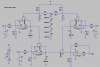
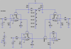
I run across the schematic shown in page 13 of the RC4136's datasheet (attached). After 3 days trying to have it "working" in LTSpice (circuit attached) I realized I need help. Also attached a screen dump for those that do not have LTSpice available.

I tend to think I know the basics of log / antilog amps and I understand this circuit should give (hopefully) a Vout = Vy * Vx / Vz. Instead, the prevailing result I get is Vout slightly above Vx, no matter what Vy or Vz are.

With different op amps, or no matter how many diodes I pile up at the top (to get up to around 3.5V) to polarize the first stages, I always get a result not even close to the expected (and most of the times with >1 MHz noise riding the output).

I am puzzled by what is wrong: my simulation or the circuit?

If anyone is tempted to tell about the so many pitfalls of a circuit like that implemented with discretes or how old / lousy the RC4136 is, PLEASE don't. I am asking about a simulation and / or eventual flaw of a design.

Helps is appreciated.
 

Attachments

  • Analog multiplier 03.asc
    7 KB · Views: 256
  • RC4136.pdf
    120.4 KB · Views: 378
  • Screen for Brownie.png
    Screen for Brownie.png
    23 KB · Views: 421
Last edited:
Same result from TINA (using schematic from page 13 of datasheet):
TINAanalogMultiplier.JPG

P1 postion at 50%. Not much difference in output with change to 0 or 100%.

Also note 741 OpAmps (just keeping with the lousy component theme).

Bad circuit from Fairchild? (Wouldn't be the first...:woot:)
 
Just completed a vessel one hour ago. My weekend starts now.

A lot of effort is needed to see if I can get something "working".

Thanks for confirming that I am not simulating it wrong. Let's see how to get it working.
 
Last edited:
For starters, I looked up some other multiplier circuits.

Below is one from Linear.com - different input on x with a constant y & z and a fixed P1 gain adj. (the LT circuit used their quad opamp, the LT1079):
OpAmpMulti A.JPG

OpAmpMulti B.JPG

OpAmpMulti C.JPG

Now I'm going to see what's with the Fairchild circuit...:woot:
 
Last edited:
For starters, I looked up some other multiplier circuits.

Now I'm going to see what's with the Fairchild circuit...:woot:

Thanks for that CB!

Meantime, thanks to suggestions in another forum I got it working simply by grounding the base of Q2 & Q6.

That way I could proof that 6*20/10 = 12. Not bad, eh? In this particular circuit, as is, all the action occurs in the realm of negative values.

I can say that I finally understood how the transdiode topolgy works. Oh yes!!:joyful:
_______________________________________________________
Pending homework:

a) understand why the designer polarized the bases (Q2 & Q6) positives. :banghead: :banghead: :banghead:
b) Understand the circuits in your post. :) Where did you find them?

Gracias.

BTW: your 741's are like my pants that I bought 12 years ago: they look old and horrible but I feel OK with them! :woot: :D :D
 

Attachments

  • Analog multiplier 04.asc
    6.8 KB · Views: 186
  • Analog multiplier 04.png
    Analog multiplier 04.png
    104 KB · Views: 1,215
...

a) understand why the designer polarized the bases (Q2 & Q6) positives. :banghead: :banghead: :banghead:
b) Understand the circuits in your post. :) Where did you find them?

a): No idea: the biasing makes NO sense at all. Wouldn't be the first circuit design that was not confirmed in the real (OR SIM) world. Note that the Linear design has the equivalent bases grounded.
b): I'm going to shoot a 1Hz, 2V pk-pk sine, ridng a 1VDC bias into the "z" input and graph various nodes to see what exactly is going on. Circuit came from: http://cds.linear.com/image/460_circuit_1.jpg

BTW: your 741's are like my pants that I bought 12 years ago: they look old and horrible but I feel OK with them! :woot: :D :D

Ditto :cool:.
 
I decided that I knew little about log - antilog opamp circuits.

This: **broken link removed** helped tremendously.

As a result, my idea above [b):] was terrible and didn't work due to the time needed for the circuit of the sort I used to stabilize (often 10's of milliseconds) so a sinewave (even a slow one) was a bad idea.

Instead, I used a 1/2Hz square wave "z" input (riding a +DC bias [since this circuit will only work with positive inputs]) instead and was able to track the circuit's voltages easily. It, for the most part, now makes sense.

Been a while since I've worked with Ln values. In fact, the last time I did so I used a slide rule... :woot:
 
Agustín, a good sailor uses a soldering iron, not a simulator! :)
 
Agustín, a good sailor uses a soldering iron, not a simulator! :)

Hola Dean! Good to hear of you.

I started to use LTSpice more frequently when I face for the first time subjects I know nothing about. Hard to say why but soldering a circuit is taking longer to me than in the past. I think I should change the basics of my daily schedule.

What I like are those quick "what if" tests that LTSpice allows.

I still enjoy the building anyway!

Be well.
 
Status
Not open for further replies.

New Articles From Microcontroller Tips

Back
Top