Continue to Site

Welcome to our site!

Electro Tech is an online community (with over 170,000 members) who enjoy talking about and building electronic circuits, projects and gadgets. To participate you need to register. Registration is free. Click here to register now.

  • Welcome to our site! Electro Tech is an online community (with over 170,000 members) who enjoy talking about and building electronic circuits, projects and gadgets. To participate you need to register. Registration is free. Click here to register now.

An audio amp with the LM4780

Status
Not open for further replies.
Hi, I am making a (~300W) audio amplifier using three LM4780 chips from National.

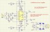
I would like to know a few things. First, in the third attachment, "LM4780 Sch", what do you think of the schematic? I ordered these as PCBs, but are there any things that could be improved? Note that the inductor labeled 0.7MH is supposed to be 7uH.

Secondly, I am in the process of choosing transformers for the design. If you have a look at the "Copy of overture design guide" it is an excell design guide by national (but i had to print screen it as it wouldnt upload), and I have entered all the values I will be using. Where it says "Ipeak" it has about 5 amps. I assume this is maximum current into the spearkers, but how can I find out the total current draw for the amps (remembering I will be using three)?

I attached the datasheet as well if it helps, but I cant see any info like max current draw, why dont manufacturers sate this?


Best regards,
Michael
 

Attachments

  • Copy of overture design guide.png
    Copy of overture design guide.png
    199.2 KB · Views: 1,093
  • LM4780.pdf
    1 MB · Views: 631
  • LM4780 Sch.jpg
    LM4780 Sch.jpg
    365.4 KB · Views: 3,104
I'm not much familiar with the IC you specified, however I'm providing some information that may come useful for you. IC need dedicated heatsinks. I think that inductor is not necessary...maybe you can replace it with a low value resistor..err

Each amps in the IC may withstand for around 6A of current...

Look here:
**broken link removed**
LM4780 Micro-Amp - Schematic
 
Thanks transistor, at this stage, the inductors are the biggest problem. I have no way of measuring the value of the coils of wire i have made, except for the estimations from online "inductance calculators".

What could they be replaced with? Could they be completely eliminated?

thanks
 
I think you've gone through those links well..

My recommendation is 2x24V,6A each power supply, so total around >250VA T. Please note the wiring of power supply. Each bridge's +ve and -ve together holds the GND, thereby leaving another +/- hot rails.

Bridge configuration will give you around 120W into single 8ohm load. I think that inductor can be completely eliminated. Wait for some more replies.
 
your recommendation of a 24-0-24 6A would be for one LM4780?, because remembering that I will be using 3 x LM4780s.
 
Last edited:
Thanks transistor, at this stage, the inductors are the biggest problem. I have no way of measuring the value of the coils of wire i have made, except for the estimations from online "inductance calculators".

What could they be replaced with? Could they be completely eliminated?

I imagine it's a class D amplifer?, in which case they are the low-pass filter to reduce the switching frequency fed to the speaker.

You say 300W, how are you planning 300W from it?.

EDIT:

Just checked the datasheet, it doesn't appear to be class-D, so there's little need for those inductors - if you wanted though, it was common practice to have a small inductor feeding the speaker, just a few turns of wire around a 1W resistor.
 
Last edited:
Yea, you need to build it for each one. One bridged mode you'll get approx 120W each for 8ohm load, then 3 amps should give total of >300W, eh..you're right :)

This is a costly project.
 
hopefully not too costly !! student budget here :) Im hoping less than $150 (AUD)

so that would be about 18 amps total needed (6x3) that sure is a bit of juice! :eek:
 
yeah, i just wanted to make sure that the schematic isnt dodgey, but most importantly, i want to find out how much three of these chips will draw. why isnt it stated in the datasheet? (or maybe i have overlooked something?)
 
For a 120W amplifer, you want roughly half as much again - so a 180W transformer.

So you're looking at a 450-500W tranformer.

For a 5.1 amplifier though, you really need a bigger amp for the '.1' (the sub-woofer), that's where most of the power is.
 
well actually, i was plaaning on only having 4 speakers and a sub. Perhaps I should bridge the third chip for a 120W sub.

Power-wise, I'll need 25-0-25, and I can get 9.2A per side, that equals 18.4A total @ 50v = 920W. I have 10A (1000W) AC outlets in australia, this should be ok, yes.

This assumes the chip can max 70W and leeway from other circuitry <1A

headroom = 4.8A, 240W

(70W * 6 chanels + 1amp other circuits)
 
So which channel are you planning leaving out?.
The centre one.

Also, I am looking at wiring separate transformers in parallel to get the power required.
I have 4* 3amp laminated style transformers and one toroidal transformer.
I realise that if the laminated transformers are the identical, they can be wired together, but what do I need to know about the 'phase' of the secondaries that are being joined?

Also, is it possible to parallel the laminated transformer with the toroid one, what will happen since they are not the same?
 
The centre one.

Are you using the TV for that?, the centre is one of the most important ones.

Also, I am looking at wiring separate transformers in parallel to get the power required.
I have 4* 3amp laminated style transformers and one toroidal transformer.
I realise that if the laminated transformers are the identical, they can be wired together, but what do I need to know about the 'phase' of the secondaries that are being joined?

Just put the secondaries in series two at a time, and measure the output across them - you can easily identify the polarity.

Also, is it possible to parallel the laminated transformer with the toroid one, what will happen since they are not the same?

Don't do it! - you can only directly parallel IDENTICAL transformers.
 
If you want to parallel them, make sure that they're identical with same rating including number of turns and all. Otherwise, the mismatch will lead to more current draw on the lower side and may heat up!

If they're out of phase, they'll cancel each other.

Do not parallel laminated one with toroidal type. What I meant is this should be done with transformer twins only.
 
Damn! what a waste of a 50$ toroid (from old amp) oh well, so I could parallel three laminated transformers to supply the power needed?

oh, and its not for the TV, nigel, the input source is only stereo anyway, and I have four speakers on hand and not five (quality ones anyway)

Any other pointers or suggestions?
 
Last edited:
Damn! what a waste of a 50$ toroid (from old amp) oh well, so I could parallel three laminated transformers to supply the power needed?

oh, and its not for the TV, nigel, the input source is only stereo anyway, and I have four speakers on hand and not five (quality ones anyway)

Any other pointers or suggestions?

Only why have multiple channels just for stereo? - it's completely pointless and makes the system sound worse than just having two channels.

If you've got three IC's use them all bridged, one for left, one for right, and the other for sub-woofer. This also provides the right impedance for most speakers, which are 8 ohm.
 
If you have two or more transformers that are almost the same, put a bridge on each of them as if you were using each as the only one. Then combine the outputs of the rectifiers at their DC terminals. It costs you extra rectifiers but makes phase a non-issue.

If the transformers are different by more than half a volt, then the stronger one will shoulder all the load and this trick is pointless. This is only good for transformers that are supposed to be the same but you aren't quite sure (same part number with subtle differences, different manufacturing lot, etc.).
 
Status
Not open for further replies.

Latest threads

New Articles From Microcontroller Tips

Back
Top