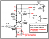
Sorry. I see what might be a transformer on your schematic. If its primary is 10k then the output of the amplifier is only 50 micro-watts max.
You should be using an LM386 audio amplifier IC. With a 9V supply it can provide about 500mW into an 8 ohm speaker, and draw very low current when not playing loudly. 10,000 times more power than your amp.
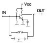
If you want to make a simple 3-transistor amp then this circuit is fairly good:
You should be using an LM386 audio amplifier IC. With a 9V supply it can provide about 500mW into an 8 ohm speaker, and draw very low current when not playing loudly. 10,000 times more power than your amp.
If you want to make a simple 3-transistor amp then this circuit is fairly good: