Continue to Site

Welcome to our site!

Electro Tech is an online community (with over 170,000 members) who enjoy talking about and building electronic circuits, projects and gadgets. To participate you need to register. Registration is free. Click here to register now.

  • Welcome to our site! Electro Tech is an online community (with over 170,000 members) who enjoy talking about and building electronic circuits, projects and gadgets. To participate you need to register. Registration is free. Click here to register now.

Amplifying an IR driver

Status
Not open for further replies.

curiouser

New Member
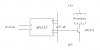
I've got a box that's designed to drive an IR emitter
(https://www.electro-tech-online.com/custompdfs/2008/08/5034NIRT20series20data20sheet2.pdf if you're curious).

I'd like to drive multiple emitters (at least 4), and I suspect it doesn't have enough power to do that (haven't been able to test it yet, but the specs say the IR port is "20 mA max rated continuous output" (and 5 V DC max) -- I couldn't find anything that said what I'd need to drive a reasonable IR emitter).

So I guess I need to amplify it. It also says "These sockets are not isolated from C-Bus and must NOT be grounded or connected to a voltage source", so I'm thinking optoisolator? But I'm a software guy, so I don't really know what I'm talking about.

Of course I could stick an IR emitter on it and then buy a $150 4-port IR distribution system... but I figure there's got to be a much, much better way!
 
IR emitter

Hi curiouser,

you're already on the right track considering an opto-isolator. Using e.g. a 6N137 you might determine the logic output high or low depending on the wiring.

Use the opto-isolator to drive a low power transistor which in turn drives the IR-LED.

The input of the opto-isolator must have common ground with the controller. For the output use separate ground.

Boncuk
 
thanks, but i'm afraid i've got less of a clue than you're expecting.

enclosed is my attempt at interpreting what you said. is this going in the right direction?

one other question... i was thinking i could just steal the 5V from a nearby wall wart that's powering another device. is that reasonable, or is the occasional 38kHz draw likely to freak out the other (microprocessor-based) device?
 

Attachments

  • Picture 3.png
    Picture 3.png
    12.9 KB · Views: 185
Hi curiouser,

the circuit is about right (don't have the 6N137 data sheet at hand presently). It should be wired the way its output is high when the receiver LED is under current. With the high output on the base of the 2N2222 it conducts and switches on the IR-emitters. Base resistor should be 1 to 2K7.


There are current limiting resistors necessary for each IR-emitter, but you might connect two times two in series. Using the TSAL6100 it is a real powerful IR-emitter with an IPCE of >100mW/sr (normal IR-emitters are at 25 to 50mW/sr)

The forward voltage is 1.3V(Uf) and the forward current (If)is 100mA.

Two examples of wiring the emitters: Two parallel pairs in series and all four parallel.

Current limiting resistors: two pairs: (5V-(2*Uf)/If), (5V-2.6V)/0.1 = 24Ω, that is two 24Ω resistors. (preferrable method)

All four parallel: (5-Uf)/If, (5 -1.3)/01 = 37Ω, that is four 37Ω resistors.

Paralleling four IR-emitters the transistor has to sink 400mA total, using two pairs of two the current is 200mA total.

Don't be worried about the 38KHz of the emitters. The MCUs frequency is much higher.

Don't forget to use a current limiting resistor for the opto-isolator as well, if none - ZAP!

Boncuk
 
Last edited:
here are a couple of versions of the datasheet:
https://www.electro-tech-online.com/custompdfs/2008/08/6N2F6N137.pdf
**broken link removed**
but i don't see any way to make it non-inverting -- am i missing something?

sorry, i don't understand any part of "Base resistor should be 1 to 2K7".

your current-limiting resistor calculations make sense, although is there any reason to not use a single 12 ohm resistor instead of 2x 24 ohm?

i was assuming that the input was already current-limited appropriately, but you're right -- i should check first...

thanks again.
 
Hi curiouser,

LEDs, also IR-LEDs require a defined forward current. Using one simple current limiting resistor for two paralleled LEDs only one of them will have the prescribed forward current. To avoid this, each branch must have its own current limiter.

I have the impression you are missing some basics concerning hardware.

Here is a complete circuit. I added a jumper to program the opto-isolator either high or low, depending on the input signal.

Building the circuit that way you'll have every option of control.

Also the manufacturers of opto-isolators don't know which voltage you'll be using for the receiver LED in the isolator. Therefor no special care has been taken limiting the forward current. With the value of R1 the forward current will be ~10mA (minimum is 7mA, max 20mA)

Regards

Hans
 
Last edited:
Sorry "Cannot find server", the usual message concerning internet in Thailand.
Here is the schematic.
 

Attachments

  • IR-LEDs.png
    IR-LEDs.png
    57.5 KB · Views: 168
OK, that helps, but i don't see how JP1 accomplishes the goal of supporting input high (which is what i need)... if i understand the datasheet, pulling pin 7 high (or just leaving it unconnected) makes the 6N137 invert the signal (which i don't want), while pulling it low leaves the output fixed high (which also doesn't help me). won't i need to do something else to invert the 6N137 output? would substituting a 2N2907 for T1 accomplish that?
 
Hi curiouser,

the logic level of pin7 determines wether the output is low or high. Therefor the jumper has the outer pins connected to VCC and ground. Set the jumper according to the desired output level.

The truth table is not describtive enough because the output is an open collector. Logically that would mean if the transistor is conducting the output would be low. Reversing that just set the jumper. Build the circuit with the jumper and try what will be the truth. The datasheet does not say anything about an unconnected ENABLE pin7. (at least mine (Toshiba) doesn't).

Here's the truthtable:

Input Enable Output
H - H - L
L - H - H
H - L- H *)
L - L - H

*) Select jumper setting to ground first

Jumper settings: 1 - 2 = Enable to ground, 2 - 3 = Enable to VCC

Once you have found the correct setting you might omit the jumper and use fixed wiring.

Hans
 
Last edited:
Status
Not open for further replies.

Latest threads

New Articles From Microcontroller Tips

Back
Top