Continue to Site

Welcome to our site!

Electro Tech is an online community (with over 170,000 members) who enjoy talking about and building electronic circuits, projects and gadgets. To participate you need to register. Registration is free. Click here to register now.

  • Welcome to our site! Electro Tech is an online community (with over 170,000 members) who enjoy talking about and building electronic circuits, projects and gadgets. To participate you need to register. Registration is free. Click here to register now.

Amplifier Ground

Status
Not open for further replies.

Quercus

Member
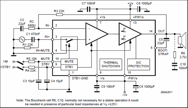
A couple of years ago, with much help from this community, thank you, I built a stereo amplifier based on a TDA7294. It's constructed of individual components on a solderable perf board. I'm now looking to build the amp again, with some additional enhancements (a bluetooth receiver, for example), and I intend to use a PCB this time.

Previously, I was having real trouble with a persistent humm. The only way I was able to solve it was to route every single ground connection back to a central point over individual wires.

I'm considering two methods of handling this on the PCB: A) Mimic my earlier solution and route each ground connection over its own trace to a central hub, or B) use a multi-layer board with an internal layer that is nothing but a single ground plane.

Thoughts or other alternatives?

Thanks.
Use both, A and B
 
A solid ground-plane will generally act the same as the individual ground wires to the single point.
But make sure you route the connections that carry the high output currents away from the sensitive input connections.
Flooding the unused area around the traces on the other layers with copper connected with vias to the ground-plane, will also help reduce noise.
Decouple all the power pins directly to ground with 100nF ceramic caps.
 
Decouple all the power pins directly to ground with 100nF ceramic caps.
By this, I presume you mean the Vs+ and Vs- pins on the TD7294 and related op-amps. Each pin is connected to ground via its own 100nF cap, placed as physically close to the component's pin as space allows. If you mean something different, please clarify.

Flooding the unused area around the traces on the other layers with copper connected with vias to the ground-plane

My interpretation here is to use a copper pour on the top and bottom layer, connected to the ground plane with only a few scattered blind vias. The pour on the top and bottom layers would NOT be connected directly to any of the components or their respective ground pins to avoid any ground loops. The components would only be connected to the ground plane. Is this the implementation suggested?

Thanks.
 
Why not just google for TDA7294 PCB examples?

Here are a couple of the many hits.


It would be unusual to use ground planes on audio power amplifiers, it's not something that's commonly done.
 
Did that. Also reverse-engineered a couple of amps in the house. All basically use a star pattern (option A). But I'm still interested in other options and would like to learn from the input of others in this community.


Why?

Because it's more an RF technique than an audio one.
 
A) Mimic my earlier solution and route each ground connection over its own trace to a central hub
this is what most manufacturers do, they do not use multilayer boards, but they do use double sided boards occasionally.... Yamaha, Sony, Denon, etc... all use single sided boards in their amp sections and a "star" ground.... IIRC a couple of them have a "star ground" component that is a copper ring with a bunch of legs that gets populated and wave soldered onto the board to join all of the ground points.
 
Status
Not open for further replies.

Latest threads

New Articles From Microcontroller Tips

Back
Top