Continue to Site

Welcome to our site!

Electro Tech is an online community (with over 170,000 members) who enjoy talking about and building electronic circuits, projects and gadgets. To participate you need to register. Registration is free. Click here to register now.

  • Welcome to our site! Electro Tech is an online community (with over 170,000 members) who enjoy talking about and building electronic circuits, projects and gadgets. To participate you need to register. Registration is free. Click here to register now.

Amplifier gain not stable

Status
Not open for further replies.

Chengjun Li

New Member
I found an amplifier board which was made by someone else several years ago.
6419634800_1455308000.png

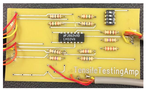
The function of this board is to amplify the output signal of a linear displacement sensor in a tensile testing system.
The schematic is shown below.
1566675800_1455308049.jpg

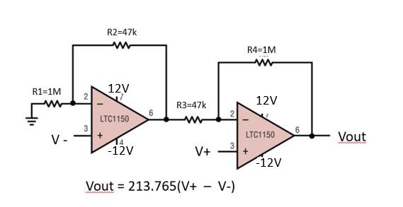
The ideal gain is 213.765 by using the equation Vout = (V+ - V-) *(R1+R2)/R2 with R4=R1 and R3=R2.(typo, R1=R4=10M actually)
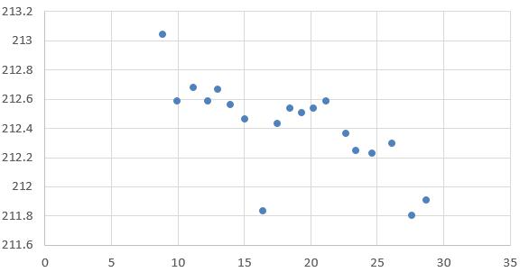
However, I made a simple measurement and found that as the input voltage(V+ - V-) increases, the gain decreases.
8929319700_1455308080.png


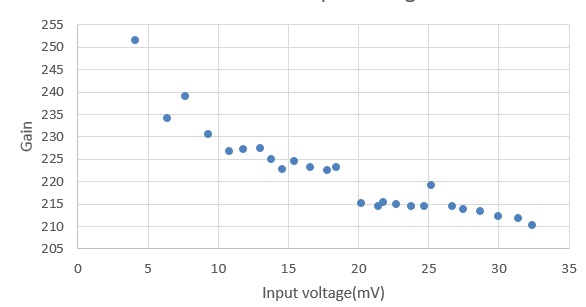
There are two sets of instrumentation amp in this board, I test both, and they both show above phenomenon. So I don't think it's the board's problem, I think there must be something I did wrong which lead to this strange result.

The steps I did are like following:
1. I connect the excitation input of the linear displacement sensor to 5V power supply.
2. I connect the signal output of the linear displacement sensor to the V+ and V- of the amplifier board.
3. I power the amplifier board with a 12/-12V dual power supply.
4. I connect the 12/-12V power supply's ground to the ground of 5V power supply.
5. I change the signal output of the displacement sensor(input to the amplifier board) and measure the output of the amplifier board, then calculate the gain.

Could anyone tell me what I did wrong? Why the gain is not stable?

Thanks.
 
Last edited:
It may be the DC offset of the amp affecting you measurements.
What is Vout with both inputs grounded?
You need to subtract that voltage from your measured voltages to get the correct gain.
 
The photo shows a lousy old LM324 with plenty of input offset voltage and the schematic shows LTC1150 opamps that have sample and hold circuits that cancel any input offset voltage. A HUGE difference.
The LM324 cannot use resistors with a value as high as 10M.
 
It may be the DC offset of the amp affecting you measurements.
What is Vout with both inputs grounded?
You need to subtract that voltage from your measured voltages to get the correct gain.
Thanks a lot for your reply. I did a test, when the input is 0, the output is less than 70mV. The offset might not be the problem.
 
The photo shows a lousy old LM324 with plenty of input offset voltage and the schematic shows LTC1150 opamps that have sample and hold circuits that cancel any input offset voltage. A HUGE difference.
The LM324 cannot use resistors with a value as high as 10M.
I am so sorry for the confusion. The opamp actually is LM324. I grab the schematic LTC1150 from internet.

The real board contain two sets of the schmatic circuit, one is used to amplify the displacement signal, the other is used to amplify force signal. The board circuit and schematic is the same. Not quite understand your word" huge difference".

I measured the resistance of these resistors on board without desolder them. The R1 is around 6M, and R4 is around 2.5M.
But based on the color code, they should be both 10M.
 
The LM324 quad opamp is cheap, old and has poor performance. The LTC1150 opamp is much better and they have a HUGE difference in performance in that circuit that is designed to use the LTC1150 opamps.
The larger photo you posted on the other website shows that the cheap carbon film resistors are damaged. Undamaged metal film resistors will be more stable.
 
Thanks a lot for your reply. I did a test, when the input is 0, the output is less than 70mV. The offset might not be the problem.
"Might not be" is not an engineering answer. :rolleyes:
You won't know the true magnitude of the problem until you recalculate the gains with the offset removed.
 
The LM324 quad opamp is cheap, old and has poor performance. The LTC1150 opamp is much better and they have a HUGE difference in performance in that circuit that is designed to use the LTC1150 opamps.
The larger photo you posted on the other website shows that the cheap carbon film resistors are damaged. Undamaged metal film resistors will be more stable.

Usually true. You can design for the LM324 and achieve serviceable results. It's a matter of precision and repeat-ability vs additional calibration methods.
I am using an LM324 in instrumentation 'mode' with 3 OPA and can get about +/- 0.03V accuracy across a 3V to 20.48V range with 10 bit ADC sampling (oversample to 12bit) and offset calibration control. My goal is average voltage (pi RC filter) over 32mS periods which is fine for the LM324. Fast slew OPA would add aberration to the readings as I am using PWM to drive the voltages.

If you need accuracy close to 0V etc, another OPA is called for with a dual rail.
 
"Might not be" is not an engineering answer. :rolleyes:
You won't know the true magnitude of the problem until you recalculate the gains with the offset removed.
You are correct, it is the offset problem. I substract the initial offset and calculate again, I got the following result which improved a lot.
5279081800_1455464691.jpg


You teach me a class. Initially I ignored the offset because I thought 70mV is too small comparing with several voltage output, later when I drive back home, I suddenly realized that the input is on the mV scale. After I did the calculation, I got the correct result.
I should be more careful as an engineer, I won't tell a conclusion before I actually do it in future.
 
.........................
You teach me a class. Initially I ignored the offset because I thought 70mV is too small comparing with several voltage output, later when I drive back home, I suddenly realized that the input is on the mV scale. After I did the calculation, I got the correct result.
I should be more careful as an engineer, I won't tell a conclusion before I actually do it in future.
Sounds like a good lesson learned. :)
It's always dangerous in engineering to make assumptions about the affect of some parameter on the system without actually determining what the quantitative effect is.
 
If your sig. levels are that low, you should look at your quantitative supply noise floor to refine your accuracy.
 

Attachments

  • _Reducing Voltage Reg Noise.pdf
    1 MB · Views: 225
The lousy old LM324 and cheap damaged carbon film resistors are very noisy.
 
Status
Not open for further replies.

Latest threads

New Articles From Microcontroller Tips

Back
Top