Continue to Site

Welcome to our site!

Electro Tech is an online community (with over 170,000 members) who enjoy talking about and building electronic circuits, projects and gadgets. To participate you need to register. Registration is free. Click here to register now.

  • Welcome to our site! Electro Tech is an online community (with over 170,000 members) who enjoy talking about and building electronic circuits, projects and gadgets. To participate you need to register. Registration is free. Click here to register now.

amplifier for MW 520kHz using ferrite core

Status
Not open for further replies.

earckens

Member
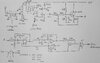
Would the use of a ferrite core be allowed to be used in the part of the schematic attached, instead of the drawn dipole (with the RF coil ("2F trafo" in schematic) tuned to 520kHz )?

I would attach one end of the coil on the ferrite core to the 100nF cap, and the other coil end to ground.

Purpose is to amplify signals on 520kHz only.
 

Attachments

  • michael_hompus_Navtex_antenna-amplifier.jpg
    michael_hompus_Navtex_antenna-amplifier.jpg
    505.7 KB · Views: 264
Last edited:
Of course, as used in almost every MW radio, with suitable windings to match the aerial impedance.

Usually the main tuning winding is high impedance, and tuned via a large variable capacitor, with a low impedance winding feeding the following transistor. As this is an FET stage you should be able to directly connect the main coil to the FET.

To add an external aerial as well, you simply add another low impedance winding on the ferrite rod, to match the (supposed 50/75 ohm) impedance of the aerial to the tuned circuit.

So one coil only around the ferrite core is not ok?

Currently I have 72 windings, corresponding to around 500kHz, feeding into the 100nF cap (the first cap on the drawing).

How many windings should the second coil have?

Great info Nigel, on adding the external (dipole?) antenna.
 
So one coil only around the ferrite core is not ok?
A little bit small, I think.

Currently I have 72 windings, corresponding to around 500kHz, feeding into the 100nF cap (the first cap on the drawing).
How many windings should the second coil have?
I would start with 7 turns for the second winding on the ferrite rod.
ie 10% of the main (tuned) winding.

JimB
 
I think we read what he put completely differently :D
Sounds like another attack of semantic differential!

In JimB speak
Winding = Coil
as in the primary and secondary windings of a transformer.

Turn = a 360 degree circle of wire.

JimB
 
Status
Not open for further replies.

Latest threads

New Articles From Microcontroller Tips

Back
Top