Continue to Site

Welcome to our site!

Electro Tech is an online community (with over 170,000 members) who enjoy talking about and building electronic circuits, projects and gadgets. To participate you need to register. Registration is free. Click here to register now.

  • Welcome to our site! Electro Tech is an online community (with over 170,000 members) who enjoy talking about and building electronic circuits, projects and gadgets. To participate you need to register. Registration is free. Click here to register now.

"Amplifier Circuit"Need Help!!!

Status
Not open for further replies.

hoangnguyen

New Member
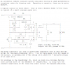
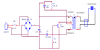
I must do a project about "Ultrasonic Bath"but i don't have any experiences in this field. Please help me with this circuit:**broken link removed**
How can we choose the number of wire-ring of the primary and secondary of the transformer to get the maximun Frequency of the Tranducer?
Pls help me!
(Show me some website related to this one is OK)
 
Last edited:
The link to your circuit does not work. Instead of a link why not attach the schematic to your reply here?
 
sorry about the link of circuit!
Here i attach the circuit for you! Pls help me!
Thanks so much!
 

Attachments

  • circuit.png
    circuit.png
    23.4 KB · Views: 1,447
Look at Blocking oscillator in Google.
Most circuits oscillate at only 400Hz which is too low.
 
I made a 'joule theif' earlier in the week, it's a simple blocking oscillator and it's running at around 50khz
 
Last edited:
I made a 'joule theif' earlier in the week, it's a simple blocking oscillator and it's running at around 50khz

Thanks for reply!
But can you show me something more detail? Let's consider that the frequency is about 50khz. But how could we choose the number of wiring for the Primary and Secondary of the transformer to get that frequency?
Pls show me something more! Thanks
 
More turns means more inductance means slower frequency. The transistors capacitance and the inductors inductance at the operating current will determine the ultimate frequency this is generally something you guess at, if you need a sepcific frequency there are better oscilators.
 
Last edited:
More turns means more inductance means slower frequency. The transistors capacitance and the inductors inductance at the operating current will determine the ultimate frequency this is generally something you guess at, if you need a sepcific frequency there are better oscilators.

You mean that "if the turns is higher then the frequency is lower"? So how could we know that where is the best of the turns?
You've already said that you did a project and your frequency is about 250khz so how about your turns? Can you give me some information about your project
 
250? No it was about 50k.
It was approximately 20 turns of 30 gauge wire wrapped as two stacked coiles on a toroid.
 
The "Joule Thief" for an "Ultrasonic Bath"? :)

ken
 
The Joule thief has a 1.5V battery and has an output power of about only 0.0075W. It uses a low voltage, low current little transistor.

Your ultrasonic bath circuit uses a 323V supply (the 230V mains rectified) and has an output power of maybe 7.5W or more.
Its 2SC3688 big power transistor is used to make the horizontal deflection and high voltage in a colour TV and is rated at 1500V, 10A and switches very fast.

Your transformer probably has a ferrite core, has very low capacitance and is probably a voltage step-UP type.

Edit: The schematic of an ultrasonic cleaner circuit is in Google. It uses a high voltage, high current and high power transistor and a transformer with a ferrite core. it recifies the 120V mains to make a pulsing 169V supply. The schematic is in old text:
 

Attachments

  • ultrasonic cleaner.PNG
    ultrasonic cleaner.PNG
    30.1 KB · Views: 1,306
Last edited:
audioguru, not suitable for an ultrasonic bath obviously but the joule thief I made puts out 50ma's into a diode with 3.1 volt drop, that's 150mw's.
 
audioguru, not suitable for an ultrasonic bath obviously but the joule thief I made puts out 50ma's into a diode with 3.1 volt drop, that's 150mw's.
The average current and power in the LED is pretty low because the pulses are very narrow. Then a little AA alkaline battery will power the Joule Thief for hours a night and for weeks.

The original Joule thief used 38AWG wire wrapped on a tiny little ferrite bead. They say it has enough light to read in a dark room, not much light.
A copy uses 24AWG telephone wire wrapped on a huge ferrite torroid and it makes an LED extremely bright and quickly kills an AA battery cell.
 
Status
Not open for further replies.

Latest threads

New Articles From Microcontroller Tips

Back
Top