Continue to Site

Welcome to our site!

Electro Tech is an online community (with over 170,000 members) who enjoy talking about and building electronic circuits, projects and gadgets. To participate you need to register. Registration is free. Click here to register now.

  • Welcome to our site! Electro Tech is an online community (with over 170,000 members) who enjoy talking about and building electronic circuits, projects and gadgets. To participate you need to register. Registration is free. Click here to register now.

Amplifier abilities confusion

Status
Not open for further replies.

cchalmers

New Member
Can you help me. I am fairly rubbish at analog amps and have a problem with a LM8272MM national chip. It is an unlimited drive op amp for driving a capactive load. My set up is as follows,

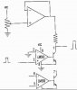
I have a +20V supply connected to Vs+ ( pin 8). I have zero volts
connected to Vs- (pin 4). I am using the amplifier in a non inverting setup. I have my input of 5V going to V+ (pin 5). I am using negative feedback. I have a feedback resistor of 20K between the output (pin 7) and the Vin- port (pin6).

I have another resistor from Vin- port (pin 6) to ground of 5K. This
gives me a gain of 4.

My input is an ac signal of 10KHz going from 0V to 5V. It is a square
wave.

I thought I would get a 20V signal going to 0V to 20V at a frequency of
10KHz on the output but all I am getting is a 0 to 10V signal of 10KHz.

Why am I only getting a gain of 2 instead of 4??? ( I have checked the resistors are actually the said values)


I know that its one of these common mode voltage verus gain things but I can't find anything in the datasheet to indicate what the problem is. National have refused to help me.

I would appreciate anyone's help. Thanks in Advance

Chris :roll:
 
Try posting the circuit, it sounds like you probably aren't setting the DC conditions correctly on the chip. Opamps are usually designed to work off split supplies - to use them on a single supply you usually have to generate a split supply for the chip artificially.
 
I thought you'd be fine with a single supply so long as your output didn't go outside the bounds of the rails. Is this wrong? I've used an opamp to generage 0v to 5v signals before, and just used 5v vcc and 0v gnd and didn't notice any problems.
 
Thanks for replying

Circuit schematic attached

When I have used op-amps at uni and at during spice they behave but
this one just doesn't have the gain I want. I have seen a similiar effect with an Analog AD623. When you use the online calculator you find that you can't use some input common input voltages because the gain inside the chip is too high that it saturates itself.

Any other ideas.
 

Attachments

  • AMP_586.jpg
    AMP_586.jpg
    21.7 KB · Views: 562
As I thought, the DC conditions are totally wrong, it's only because you are feeding it a square wave that it looks to have low gain - it will actually be distorting and clipping on the HT rails (or at least on one of them).

To make it work properly you need to add a few extra parts.

1) Add a capacitor in series with R4, this will drop the DC gain to 1, and stop the feedback upsetting things.

2) Add two identical resistors on the input, one to +ve, and one to ground, this will bias the opamp midway between the supply rail and ground (effectively making a split supply). These set the input impedance of the stage, so you need to know how high it needs to be - I would suspect 100K each would probably be OK (giving a 50K input impedance).

3) Add a DC blocking capacitor in series with the input, this will stop the signal source affecting the DC conditions set by the two resistors.
 
cchalmers said:
<snip>I am using negative feedback. I have a feedback resistor of 20K between the output (pin 7) and the Vin- port (pin6).

I have another resistor from Vin- port (pin 6) to ground of 5K. This
gives me a gain of 4.<snip>
Noninverting gain is 1+Rf/Rs. Your gain is 5.
 
Thank you nigel and Ron. I appreciate your help. I indeed tried what nigel suggested and it worked. I have one more question which should be straight forward enough.

After Nigel's suggestions I have an output signal of 100KHz with a PK to PK size of 20V. 0V to 20V. However when I reduce the gain down to 2, I get a signal 10V PK to PK but at a dc offset of 10V. What I want is a signal 0 to 10V. I want the offset to change with the gain so it is always 0V to my peak value.

Any ideas

Thanks in advance

Chris
 
cchalmers said:
Thank you nigel and Ron. I appreciate your help. I indeed tried what nigel suggested and it worked. I have one more question which should be straight forward enough.

After Nigel's suggestions I have an output signal of 100KHz with a PK to PK size of 20V. 0V to 20V. However when I reduce the gain down to 2, I get a signal 10V PK to PK but at a dc offset of 10V. What I want is a signal 0 to 10V. I want the offset to change with the gain so it is always 0V to my peak value.

Simply feed it through a capacitor at the output, this will remove any DC offset.
 
Nigel, yeah thats what I thought. I put a 0.1uf cap on the output and then measured it on the scope. The gain has completely gone. There is a 5V PK to PK signal on the scope. just below 0V to 5V. I tried putting a load resistor on the end of it to see if it was happier then but its not. I took the cap off and it had the correct signal on the output again. Why should this not work?
 
cchalmers said:
Nigel, yeah thats what I thought. I put a 0.1uf cap on the output and then measured it on the scope. The gain has completely gone. There is a 5V PK to PK signal on the scope. just below 0V to 5V. I tried putting a load resistor on the end of it to see if it was happier then but its not. I took the cap off and it had the correct signal on the output again. Why should this not work?

You haven't connected it from the output to ground have you?. It should feed from the output to whatever you are feeding.
 
The coupling capacitor converts the varying dc signal to ac, so you should have +-5 volts out.
If what you want to do is vary the pulse amplitude, this circuit will be more straightforward: I used the LM393 because the symbol was available, I don't know if it is fast enuf for your application.
 

Attachments

  • pulseamp.jpg
    pulseamp.jpg
    10.5 KB · Views: 521
Perhaps if you could explain why you want to amplify the 0-5v signal (and can decide how much gain you really want), there may be a solution that does not even involve an op amp.
 
cchalmers said:
Nigel, no I haven't connected it to ground. It comes from the output to cap and on to the scope probe.

Well it shouldn't affect the amplitude at all - as Russlk pointed out, adding a capacitor like that will give you a signal centred at ground level, swinging positive and negative of ground (I didn't read your question correctly!).

What actually are you trying to do here?, perhaps we could suggest an easier way?.
 
I am trying to amplify a 100KHz signal that comes in as a 0V to 5V signal (TTL). It has to amplify the signal to a 0V to 20V signal. However, I want to be able to change the signal to a 0V to 10V signal or a 0V to 12V signal etc etc... i.e. the output must be a 0V to something voltage. I envised this as being changable via the gain of the amplifier.

The only complication is that I need an amp that can drive capacitive loads as it is driving a big liquid crystal cell. Thats why I chose the chip I did because it has unlimited current drive.
 
If you connect a diode, anode to ground, after the coupling capacitor, it will prevent the signal from going more than .5 v negative. Alternativly, you could use a transistor switch, driven by the inverted input signal to clamp the output closer to ground.
 
cchalmers said:
I am trying to amplify a 100KHz signal that comes in as a 0V to 5V signal (TTL). It has to amplify the signal to a 0V to 20V signal. However, I want to be able to change the signal to a 0V to 10V signal or a 0V to 12V signal etc etc... i.e. the output must be a 0V to something voltage. I envised this as being changable via the gain of the amplifier.

The only complication is that I need an amp that can drive capacitive loads as it is driving a big liquid crystal cell. Thats why I chose the chip I did because it has unlimited current drive.
Go back to your original schematic and change R5 to a 10k pot (connected as a rheostat/variable resistor) in series with a 5k resistor. For an input of 0 to 5v, your output will now vary 0-10v to 0-20v, depending on the pot setting. You don't need DC blocking capacitors or clamps.
The LM8272MM does not have unlimited output current capability. It can work with any capacitive load, which just means that it won't oscillate as some op amps will with a capacitive load. You'll still have risetime degradation with large capacitive loads.
 
Thank you Rus, Nigel and Ron. I appreciate all your help regarding this problem I was having. The first solution proposed by Nigel and Rus did do the job I wanted it to with the output able to drive the load I required.

Ron's Solution also works with less bits. It does exactly what it says on the tin.

Ron, I am slightly confused by why this works and didn't before. Are we just increasing the gain on the top half of the signal and just letting the bottom half get clipped?

Thanks again guys
 
cchalmers said:
Thank you Rus, Nigel and Ron. I appreciate all your help regarding this problem I was having. The first solution proposed by Nigel and Rus did do the job I wanted it to with the output able to drive the load I required.

Ron's Solution also works with less bits. It does exactly what it says on the tin.

Ron, I am slightly confused by why this works and didn't before. Are we just increasing the gain on the top half of the signal and just letting the bottom half get clipped?

Thanks again guys
I have no idea why it didn't work before. You had a gain of 5, which would have driven the amplifier into limiting when the input was at 5 volts, but that should not have caused the output to limit at 10 volts.
And no, we are not "increasing the gain on the top half of the signal and just letting the bottom half get clipped". The amplifier is linear. Remember that, for any gain, zero volts multiplied by the gain is still zero volts.
 
Status
Not open for further replies.

Latest threads

New Articles From Microcontroller Tips

Back
Top