Continue to Site

Welcome to our site!

Electro Tech is an online community (with over 170,000 members) who enjoy talking about and building electronic circuits, projects and gadgets. To participate you need to register. Registration is free. Click here to register now.

  • Welcome to our site! Electro Tech is an online community (with over 170,000 members) who enjoy talking about and building electronic circuits, projects and gadgets. To participate you need to register. Registration is free. Click here to register now.

Amp driving LEDs project

Status
Not open for further replies.

Faradave

Member
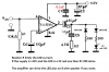
Okay so I've been working on this for quite some time. For me this is a rather large project. I'm taking an amp but instead of speakers giving LEDs to light. I want to make two of them for an electric guitar and violin so that any sound they produce will cause this led to light. So easy a caveman could do it right? 2 f***in months later..... Here I am.... Anyways here's the setup I'm using. I will either splice into the existing or add a little Piezo pickup. Those both work. And they will lead to this TDA7231A amp:
Screenshot_20191210-151426.png

And just instead of speakers I put one LED. I should also let you guys know that one of those capacitors seems to be without polarity. I did not have that value so I created one bye connecting two capacitors of double the value in series. I was told that this would create a capacitor of half the value of the two combined but with no poles. It's the best amp I've ever built anyways, with the most gain and least noise. This works great for one or two notes. Then it just seems like there's a capacitor that giving this LED power and it starts out strong but slowly Fades. Then if you leave it alone for a long time and give it a chance to charge, it works again. It takes a long long time to charge. I've even tried connecting the speaker output as the triggering current for a transistor that should allow a good 3 or 4 volts to flow no. But it doesn't it behaves the same way. I'm pretty sure I'm connecting the transistor correctly, maybe not. Here's what it looks like fully connected with a transistor that seems to do nothing but working, if for only the first few notes:
20200128_155802.jpg

I thought about using a relay instead but I don't have any with an activation voltage low enough. It would be nice if it was a dim light for quiet noises and a bright light for loud noises oh, but I would settle for just light at 1 brightness for any sound. I just can't get this for more than a few notes and then it needs to recharge. What can you guys suggest? Perhaps changing one of the capacitors? I've fiddled with this so long it would be a shame not to get it working. I appreciate y'all's help.

Edit: oh and I did try adding another amplifier between the LED and the first amplifier. Oddly, the same thing happens. There is no amplification. The LED works for the first few notes then quits. I don't get this, amps amplify.
 
Last edited:
Why on your schematic are both the amplifier's inputs, its output and its positive power supply are all shorted to ground??
Do it like this:
 

Attachments

  • amplifier blinks LED.png
    amplifier blinks LED.png
    34.7 KB · Views: 198
Your transistor has no part number but it looks like the amplifier output blows up the base-emitter of the transistor because a resistor is missing to limit the current, and the transistor blows up the LED because another resistor is missing to limit the current.
 
That transistor is C2621, it calls itself a power transistor. I recall correctly, the speaker ground and the input ground are all wired to the same ground as the power supply. Is that not good? That's what the datasheet said to do and it's still the best amp I've built yet. I'll try out your configuration and see what happens. You feel like that would give me a consistent power output to that led? Right now, it gives the perfect amount of power to the LED but only for a few bursts. That's why it kind of feels like a capacitor is at fault.

When I measure the voltage output with no LED or speaker connected, I'm lucky to get a half a volt Max. I don't think it's blowing through the transistor and I know it's the perfect amount for the LED at first. Then it decreases
 
oh, in this pic:
20200128_155802.jpg

that 2.8V is just to power the LED. you can't see it but the amp is powered by about 15V
 
An audio amp IC is not really suitable for driving LEDs and is something of an overkill in other ways.
The audio signal really needs rectifying at a low level to give a varying DC voltage, that can be used to switch one or more LED drivers.

Look at a LED "VU Meter" type circuit, even if you only use one LED output at some level threshold.

It could be as simple as this, with everything to the right of the first transistor omitted (other than the battery or power source).
These may need a preamp, probably just a single transistor stage, if the input is low level or high impedance.


356170d4abc2765c2ead5d4dd483111b.jpg


Or using an LM 319 or 339 etc. comparator, one stage of this:

LM324-vu-meter.png
 
Yeah that transistor was just something that I was trying at the time that I took that picture. It's not something that helps. Adding something to my existing circuit is fine, but building a whole new circuit can't be the right solution because then I will have wasted all that time. It mustn't be the right solution. If it's the right solution I will hit in the face.

I do have a spare 319 and 393 comparator. I've never used comparators, but they seemed simple enough oh, I'll look into that thanks.

I'll try both of yalls solutions in the order that they were received and let yall know what's up. Thanks a bunch!

Remember guys, there's no wrong answers except for the ones that I've already tried. If you feel you've got a different solution, toss it in the Hat!
 
1) Your LED has a maximum do not exceed current of only 30mA. It needs a series resistor to limit the current. Your very low 2.8V might be a weak battery that limits the current and the old 300V transistor makes a poor switch and is also limiting the LED current.

2) Your amplifier or 15V power supply is defective or is turned way down to produce an output of only 0.5V. Maybe the output of the amplifier is destroyed by trying to drive the base-emitter of the transistor without a series resistor to limit the massive current that would be produced. Its absolute maximum allowed current is only 1A that would easily be exceeded when shorted by the base-emitter of a power transistor. Maybe your AC meter cannot measure frequencies higher than 60Hz? Most cannot.
The datasheet for the amplifier shows that its maximum output power with your 15V supply into a speaker is 1.8W without clipping. A simple calculation show it producing plus and minus 5.4V peaks which will easily drive an LED that has a series resistor to limit the current like I showed. I added a diode in series with the LED to block the minus voltage at the output of the amplifier's 470uF capacitor from blowing up the LED that must never be fed a negative voltage.
You had a problem of the LED lighting only a few times then not lighting. It is because the LED conducted current when the signal went positive that charged the 470uF capacitor then when the signal went negative the LED did not conduct to discharge the capacitor, causing the capacitor to keep charging until the LED would not light anymore. My circuit fixed that with the second diode reversed and in series with the 330 ohm resistor to discharge the 470uF capacitor each time the signal went negative.

3) If you want the LED to change its brightness with the loudness of the amplifier then you need a circuit that can vary the LED's current, not vary its voltage like this amplifier does.
 
Well that half a volt output is with the guitar as input, which has a really low output and needs a preamp for regular amps to pick it up. When I connect it to my phone or computer oh, something that has a volume control, I can get much more volume out of it although it's fuzzy volume at certain levels. That 7231 amp is either real powerful or also has a preamp built into it. It's the first one I've built that could pick up a guitars output. Man you're pretty good at this stuff though aren't you? I can't wait to try that circuit out. Yeah I figured there was a voltage / current mismatch with that transistor. It never changed a darn thing.

And yeah I guess I was hoping the current was being varied as well. I'm aware that current is the most important thing for LEDs.

In order not to have wasted weeks worth of free time, I'm going to try to make your amp circuit work. Failing that, I'll see what's up with Vu meters Etc. Thanks a bunch man!
 
OK, here is an example.

I do not have a plug-in prototyping board so I've done it on stripboard with the copper side up and the components standing well off it, so all connections are visible:

The video is a bit rough, holding the phone in one hand and reaching a guitar propped on a chair with the other...

Link: Video demo on youtube

Detailed photos of the device:
IMG_0396.JPG
IMG_0397.JPG
IMG_0398.JPG
IMG_0399.JPG
IMG_0400.JPG

All capacitors are 10uF.
The other components are, left to right:

Preamp:
470K upper and 100K lower, base bias.
4K7 collector to power, 1k5 emitter to 0V.

Rectifier:
Two 1N4148 diodes

LED driver:
33 Ohm emitter to 0V, 220 Ohm collector to LED cathode.

The LED anode is to power.

The transistors are generic NPN ones, actually 2N3904's out my parts box.
The only cuts in the stripboard tracks are the two visible near the centre, between the preamp and rectifier sections.
If it's not clear, the left hand wires are to a 1/4 jack socket, 0V to ground and the right hand to a PP3 battery clip, negative to 0V.


In practice, the 10uF on the output of the rec (base of the LED driver) is rather too large, which is probably why there is a delayed action effect... A 0.1uF (100nF) would probably work rather better.
It looks like that ancient transistor is also slightly leaky, as the LED never completely goes out.
A 1M from base to 0V would also be an improvement.

But, it works, to show how simple something like this can be!
[It took me longer to figure out how to get the video on youtube in the correct orientation than it did to build the thing!]
 
Well that half a volt output is with the guitar as input, which has a really low output and needs a preamp for regular amps to pick it up.
No, your transistor circuit overloaded the guitar pickup which reduced its output level.

That 7231 amp is either real powerful or also has a preamp built into it. It's the first one I've built that could pick up a guitars output.
No, it is not powerful, instead it is sensitive. Its datasheet says its input to output voltage gain is 38dB (almost 100 times). The 10k resistor at its input is also overloading a guitar pickup but the amplifier's high gain lets it work (but the 10k resistor causes a guitar pickup to sound muffled without high frequencies).
 
most guitar pickups have about 50k or more output impedance, which is why volume pots on guitars are usually 100k to 500k.
 
Most electric guitar amplifiers have a 1M input resistance so they can produce the "twang" high frequencies of the pickup resonating with cable capacitance.
This amplifier has a 10k input resistor that overloads the pickup and muffles the high frequencies like this:
 

Attachments

  • Guitar pickup peak.PNG
    Guitar pickup peak.PNG
    73.1 KB · Views: 173
  • guitar preamp.PNG
    guitar preamp.PNG
    15.4 KB · Views: 170
Status
Not open for further replies.

Latest threads

New Articles From Microcontroller Tips

Back
Top