Continue to Site

Welcome to our site!

Electro Tech is an online community (with over 170,000 members) who enjoy talking about and building electronic circuits, projects and gadgets. To participate you need to register. Registration is free. Click here to register now.

  • Welcome to our site! Electro Tech is an online community (with over 170,000 members) who enjoy talking about and building electronic circuits, projects and gadgets. To participate you need to register. Registration is free. Click here to register now.

Advise on how to use a PIC. To Control a Calender Dial

Status
Not open for further replies.

markelectro

New Member
Advice on how to use a PIC. To Control a Calender Dial

Hello everyone.
I am seeking advice on a little project I have in mind.I may find it a little hard to explain due to my lack of knowledge with PIC's but I will try my best.

The project I have in mind is to build a Mechanical and PIC.controlled calender clock/dial.

The calender clock dial will be run mostly from an Electro Mechanical impulsed movement that has a 31 toothed wheel (for max 31 days in a month)the movement is Electronically impulsed once every 24 hours so it is easy to get the calender dial to indicate the days up to 31.The hard bit is when the days of the month go to 28 or 30 now the wheel count can't do this.
My Idea was to have a PIC follow the natural flow of the electro movement and add on extra impulse only where required.

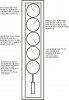
The chart in the attached file shows the months and the 1's are for the impulses required each day( 24 hrs) The red 1's show where the PIC will have to add a pulse so the count always adds to 31.(I hope you can read the file,I will email you it if you can't)

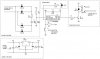
I think because the Calender clock receives an impulse to work the electro magnets that move the 31 toothed wheel a PIC. should be able to follow this pattern and could make adjustments where required.

I hope someone can help with this one.I have just picked up a Pic training course and hope to trial this project.

Regards Mark.
 

Attachments

  • Image2.jpg
    Image2.jpg
    47.5 KB · Views: 196
Last edited:
Hi, you must keep in mind that you have to implement a gregorian calendar in software to have 365 and 366 days/year to know if the current February month have 28 or 29 days.
You can do it using some different methodes.
For instance, as you know the year 2000 it was one leap year.
So, 2004, 2008, 2012 are leap years.
If your PIC calendar starts in 2000, is very easy to know if a specific year is or not the leap year.
Example: you can write a table with this years from 2000 to 2100 that results in 25 values; 0x00, 0x04, 0x08, 0x12...
Whenever he will be 28 of February, before passing to 1 of April, we go to see if the year is leap, by comparing the present year with the table.
IF the result TRUE, the next day must be 29 ELSE must be April 1.
Another way is take current year value and subtract sucessively 4 until the result equal to zero or negative (result with bit 7 equal to 1).
IF equal to ZERO the year is 366 days ELSE is 365.
All this can be done in assembly.

Concerning jumping two or three days I think that your ideia is correct.

I hope this helps
Regards
 
Oh, i forget something.
The crystal must be one with very good stability.
You must consider one way to adjust the PIC to the current year.
Example: using a double 7 segment display + one keys.
If you multiplex the display you have:
7 PINS to the seven segments
2 PINS to display select
1 PIN to the KEY
1 PIN to PULSE day weel
------------------------
11 PINS --> PIC16F628A or similar.
 
Jolino

Many thanks I had thought of the leap years but I decided in my head to put a manual advance on the unit.Thinking about it whats the point of using PIC'S if I'm not using them to the full potential.I will put and advance on anyway but will also look at programming in for the leap years!!!

Would you be able to give some explinations to me on the programming required for me to use the sequance I in included,not forgetting the PIC would only have to run where it were required the Mechanics will do the rest.
I opt for mechanics because the Calender is only part of a complete clock and this is 95% Mechanics so I want it to stay as much as poss that way.

Regards Mark


jolino said:
Hi, you must keep in mind that you have to implement a gregorian calendar in software to have 365 and 366 days/year to know if the current February month have 28 or 29 days.
You can do it using some different methodes.
For instance, as you know the year 2000 it was one leap year.
So, 2004, 2008, 2012 are leap years.
If your PIC calendar starts in 2000, is very easy to know if a specific year is or not the leap year.
Example: you can write a table with this years from 2000 to 2100 that results in 25 values; 0x00, 0x04, 0x08, 0x12...
Whenever he will be 28 of February, before passing to 1 of April, we go to see if the year is leap, by comparing the present year with the table.
IF the result TRUE, the next day must be 29 ELSE must be April 1.
Another way is take current year value and subtract sucessively 4 until the result equal to zero or negative (result with bit 7 equal to 1).
IF equal to ZERO the year is 366 days ELSE is 365.
All this can be done in assembly.

Concerning jumping two or three days I think that your ideia is correct.

I hope this helps
Regards
 
Hi markelectro,
1st my apologizes for a little mistake when i refer 1 April, in fact the right is 1 March.

- Back to the original question, if i understand you right, your clock is already running, including day change pulses.
- You just need one circuit to add additional pulses in the months that have less than 31 days, right?

Imagining that you use one pic to do the job without leap year.
The pic must be syncronized with mechanics clock. I mean, the Day and Month in the Mechanic clock and in the Pic, must be the same.
This is because the pic must know in which months must generate additional pulses after follow (counting) the day change electro-mechanic pulses.

If this is what you want, i can help you writting a small piece of software to it and hardware design too, but just after you confirm this specifications to avoid working on something that serves to nothing.

Regards Jolino
 
Jolino

Your are correct with what I am looking for.The pic and the Mechanics to work together,the pic to watch the mechanics and the pic adjust where required. You are right with your explination below.

Looking forwards to your reply.

Regards Mark


jolino said:
Hi markelectro,
1st my apologizes for a little mistake when i refer 1 April, in fact the right is 1 March.

- Back to the original question, if i understand you right, your clock is already running, including day change pulses.
- You just need one circuit to add additional pulses in the months that have less than 31 days, right?

Imagining that you use one pic to do the job without leap year.
The pic must be syncronized with mechanics clock. I mean, the Day and Month in the Mechanic clock and in the Pic, must be the same.
This is because the pic must know in which months must generate additional pulses after follow (counting) the day change electro-mechanic pulses.

If this is what you want, i can help you writting a small piece of software to it and hardware design too, but just after you confirm this specifications to avoid working on something that serves to nothing.

Regards Jolino
 
As an alternative to writing the timekeeping software, you could interface the pic to a Dallas real-time clock chip such as the DS1307.

This has the advantages of taking care of the month days and leap years automatically.
And if the power were to fail for a few hours, battery backup for the rtc would maintain the time and when power is restored, the pic could read the time and re-sync the calender mechanism if needed.

Also, I think it would be a good idea to have some sort of positional sensor (similar to the slotted wheels used on a pc mouse sensors) attached to the calendar so that the pic can step the calendar back to day and month one and then re-set the date automatically if the calendar looses sync.

For the time display on the pic, you could use an lcd display that uses an HD44780 standard interface. These can be easily interfaced (see Nigel's tutorials in this forum) and bought cheaply from places such as ebay.
 
Hi picasm,
Let me tell you that, if this project was mine, i did not have doubts in choosing your solution.

Regards,
Jolino
 
Many thanks to you both for the input to this quetsion.

Both solutions sound good but I do agree that pisasm's solution sounds the bussiness!! I am at a very novice level of Electronics and would listen to any advice you both give.I would ask if you coyuld expalin the cuircuity required to run this method,if not this is ok I understand but I think off my own back I probably won't have a clue.

Regards mark


jolino said:
Hi picasm,
Let me tell you that, if this project was mine, i did not have doubts in choosing your solution.

Regards,
Jolino
 
Hi markelectro,
Original: markelectro
I am at a very novice level of Electronics
Sorry, i understand your point of view.

I don't know how is the electric circuit and with what voltage works.
If we can see it, really helps.

So, we can start with an optocoupler to read the day change pulse, one PIC12F629 (8pin) and one mini-relay to by-pass the pulse switch (integrated in your device).
Probably your clock have a power supply, can you tell us which voltage he have?

I don't know yet if you have any tool to program the pic.
Certainly the winpicprog that i see on of the moderator personal page, works.

Regards,
Jolino
 
Last edited:
Jolino
The power to the clock is 12v so I would assume that it would require it back from the circuit.
At the moment I have a trianing program for Pic programming and this can be found at-
https://brunningsoftware.co.uk/index.htm
I have all three courses.

Hope this helps Marl


jolino said:
Hi markelectro,

Sorry, i understand your point of view.

I don't know how is the electric circuit and with what voltage works.
If we can see it, really helps.

So, we can start with an optocoupler to read the day change pulse, one PIC12F629 (8pin) and one mini-relay to by-pass the pulse switch (integrated in your device).
Probably your clock have a power supply, can you tell us which voltage he have?

I don't know yet if you have any tool to program the pic.
Certainly the winpicprog that i see on of the moderator personal page, works.

Regards,
Jolino
 
Hi markelectro,
the circuit principle can be like this, however it became more simple depending on the circuit that your clock have.

Regards,
Jolino
 

Attachments

  • daysw.jpg
    daysw.jpg
    57.3 KB · Views: 174
Last edited:
Original: markelectro
At the moment I have a trianing program for Pic programming and this can be found at-
https://brunningsoftware.co.uk/index.htm
I have all three courses.

Very nice.
The c compiler are good news because the software becames more easy to implement.
When you say 12V you mean DC?

About the circuit, if you show the electric circuit, the electronics can be more simple.
Example: probably we can to take off the four diodes, opto-coupler and the relay.

Regards,
Jolino
 
markelectro,
For the interface circuit to the DS1307 and LCD there is a good tutorial provided by a forum member (Gramo). **broken link removed**

Gramo's tutorial also includes Picbasic code examples, although looking at the link to the your training kit it looks like you will either be using assembler or C.

For asm code examples for the ds1307 there is a Maxim/ Dallas application note **broken link removed**

For the LCD code, a good page is
which has several examples for various types of display.

You will need an interface to step the calendar, maybe easier to use a relay circuit to begin with see:

You will need to add a few pushbuttons to set the time, simple code that shows how to de-bounce the pushbuttons is at:


The calendar position sensor you may be able to use infra red leds and detectors from an old mouse and add a wheel that only has one slot in it to mark day or month one.
A typical sensor circuit is here: http://www.me.umn.edu/courses/me2011/robot/technotes/irbeam.html
 
picasm/jolino

Lots of usful info to follow up.I thanks you both for your inputs and I will try and put it all into practice.

If you have any more info please let me know.

Kind regards Mark
 
Hello again

Just to ask if anyone could help with an alternative Schematic for my Calender project to the one using Pic?
I do realise that this would be the longer route but It my take me some time to get my head around the Pic programming required for the complete application,unless some kind member could give me an idiot's guide to getting this going.

kind Regards Mark
 
Hi markelectro,
Very sorry, i have been very busy lately, so i don't see your message.

Back to the original question and after read all messages again...

The suggested circuit, can be more simplified if your supply will be DC.
If is the case, is important also know if the (-) is connected directly to one of the coil points and if the (+) connects to the other coil point, intercepted by the electro-mechanic switch (the one that generate the day pulse).
In this case we can remove the four 1N4148 and substitute the relay by two transistores (BC547&BC327) and a few resistors.

In the circuit, you can see one key and one Led.
This is need to tell the PIC in wich day and month is your callendar.
If you haven't this, the PIC it will never know when it must generate the appropriate pulses , right?
So, you can config this throught the key with the Led help.
I can tell you that i have a lot of circuits running like this.

Software:
Is no use to lose time before you decide if this is the solution or not.
I'm absolutely secure that this hardware will work.
When and if you decide about the electronic solution, then we can talk about software.

However i wait that you have trained some exercises in c that had certainly come with the tool that you acquired.

Regards,
Jolino
 
Many thanks for the help with the calender dail

jolino said:
Hi markelectro,
Very sorry, i have been very busy lately, so i don't see your message.

Jolino no problem at all and thanks for responding!!


jolino said:
Back to the original question and after read all messages again...

The suggested circuit, can be more simplified if your supply will be DC.
If is the case, is important also know if the (-) is connected directly to one of the coil points and if the (+) connects to the other coil point, intercepted by the electro-mechanic switch (the one that generate the day pulse).
In this case we can remove the four 1N4148 and substitute the relay by two transistores (BC547&BC327) and a few resistors.


The electromagnet does run off 12v DC. and yes with one point to (+) and the other to (-).It's just really a trnsfer of pulses going through the electromagnets,all the devices work from 12v or less the 24hr pulse is 12v and this is sent into the electro magnet with the 31 toothed wheel on it that is also 12v with one point (+) and the other point (-) so all the same.


jolino said:
In the circuit, you can see one key and one Led.
This is need to tell the PIC in wich day and month is your callendar.
If you haven't this, the PIC it will never know when it must generate the appropriate pulses , right?
So, you can config this throught the key with the Led help.
I can tell you that i have a lot of circuits running like this.

Ok I do understand that the Pic does need to know where it is and where it should be,just how to get this I don't know!!.

jolino said:
Software:
Is no use to lose time before you decide if this is the solution or not.
I'm absolutely secure that this hardware will work.
When and if you decide about the electronic solution, then we can talk about software.

Great!! I will work from your advice and confidence that this will work,after all I am asking for help.I have burned a couple of PIC'S with suscess but it's the prgram that is difficult.


jolino said:
However i wait that you have trained some exercises in c that had certainly come with the tool that you acquired.

Again Jolino due to the fact I have very little knowledge of how parts of an electronic cuircuit work together I do see this as my forts project that will hop fully take me on to other projects.I do have the Tools to Flash PIC's and a little instruction on how to programme using C and ASMB. so again learning useful things along the way. Unfortunately in these early days I do have to have things explained in a idiots guide fastion,not like I'm an idiot but simple terms makes it sink in a little better.
Could you supply a revised drawing?? and if you can please explain what each part is doing!!!


jolino said:
Regards,
Jolino

Looking forwards to your reply and further advice.

I really do appreciate your help regards Mark
 
Jolino just to give you a little insight of what I am trying to achieve I attach a little drawing of a clock I am designing.

The clock as I say is 12v although some of the slaves could run off a little less.

The Clock is a master clock with 30 and 1 sec pulses.
The clock consists of five dials-

dial 1- seconds dial (just showing seconds)
dial 2- minuet dial " "
dial 3- hour dial " "
dial 4- calender dial " "
dial 5- comparator meter

The seconds hour and minuet dials are easy for me to solve,the hour and minuets will run from the masters 30 sec output.The dials have std 30 sec slaves in them.

The Calender is where I require the help to get just right also the comparator dial I will have to think deeply about but this will be after the calender is solved.

Hope this help see where I finally want to be.
Regards Mark
 

Attachments

  • Graphic1.jpg
    Graphic1.jpg
    540.3 KB · Views: 182
Status
Not open for further replies.

Latest threads

Back
Top